When the Panoramic Blurs: Diagnosing Ghost Shadows, Bands, and Layer Errors in OPG Machines

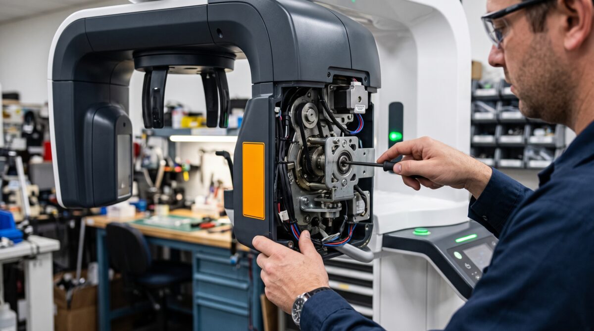
A dentist calls to say the panoramic images have “gone soft” — edges are smeared, a strange second jaw floats across the film, or a dark band marches down one side of every exposure. It is tempting to blame patient movement and move on. But a panoramic (OPG) unit is a small, precise robot: a tube-head and sensor swing around the patient in synchrony, and any drift in that choreography shows up as a predictable image fault. This guide walks the faults a service technician actually meets — ghost shadows, blur, bands, and focal-trough errors — and works each one from image physics through cause, repair, and prevention.
How a Panoramic Actually Forms an Image
Understanding the fault means understanding the exposure. In an orthopantomogram, the X-ray source and the digital sensor (or, on older units, a moving cassette) are mounted on opposite ends of a C-shaped arm that rotates around the patient’s head. The tube emits through a narrow vertical slit; the sensor reads out one thin column at a time. As the arm sweeps, the rotation centre continuously shifts along a curved path so that the sharply imaged zone follows the arch of the jaw.
That sharply imaged zone is the focal trough (image layer) — a curved, three-dimensional slice where the speed of the projected anatomy matches the readout speed of the sensor. Structures inside the trough render sharp and at correct magnification; structures outside it blur, distort, or displace. This tomographic movement is the whole trick, and it is also why the machine is unforgiving: if the mechanical sweep and the sensor readout fall out of step, the geometry that keeps anatomy sharp collapses.
Ghost Shadows: Real Anatomy Thrown to the Other Side
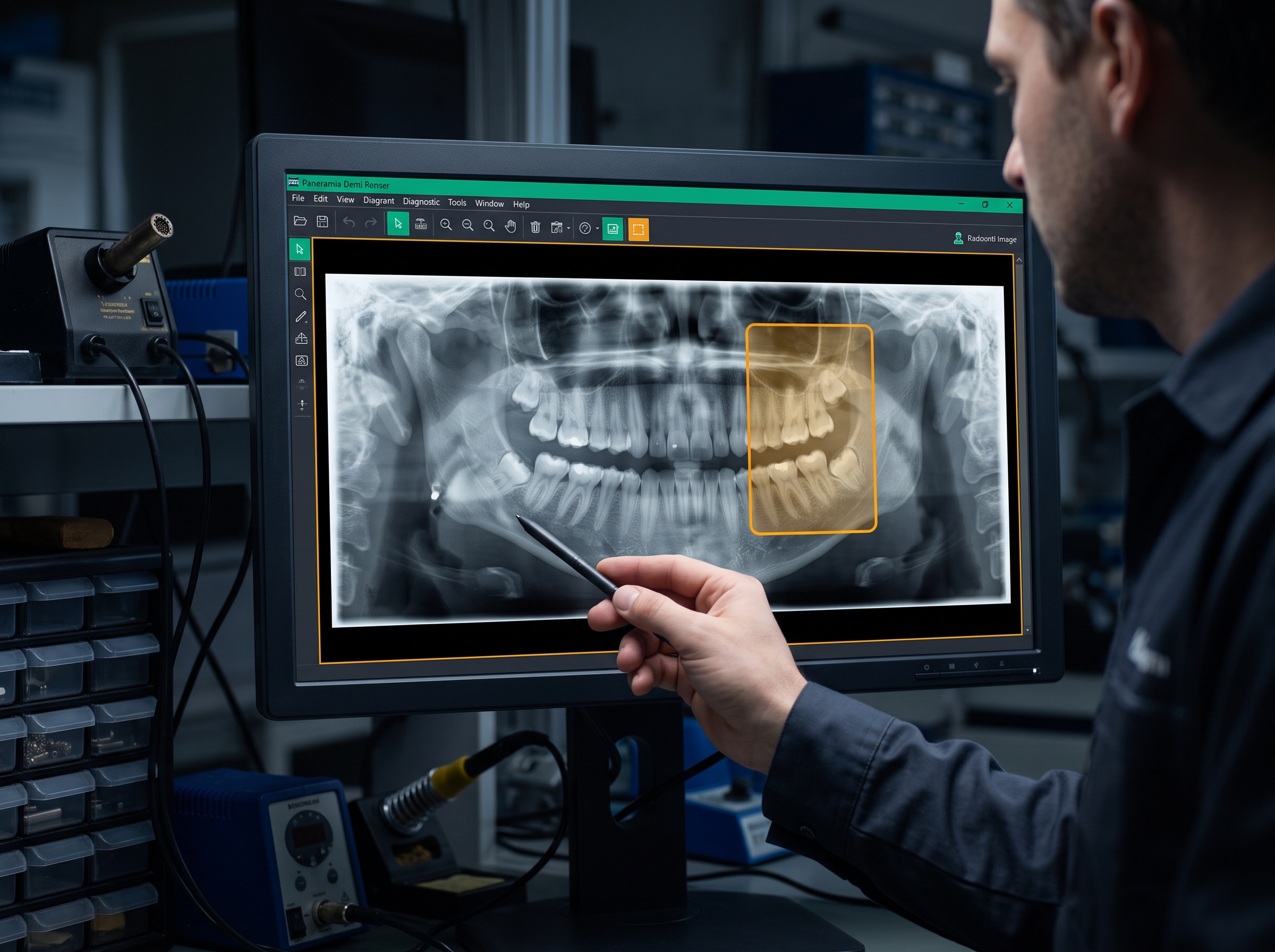
A ghost image is not a machine defect at all — it is physics behaving exactly as designed. When a dense object (an earring, a metal partial denture, the cervical spine, or the opposite side of the mandible) sits between the tube and the rotation centre on one side, the X-ray beam projects it a second time onto the sensor as the arm reaches the opposite side. The result is a duplicated, ghostly shadow with three reliable signatures:
- It appears on the opposite side of the image from the real object.
- It is magnified and blurred, because it sat far outside the focal trough.
- It slopes upward toward that opposite side, following the beam angle.
The classic culprits are earrings, dense necklaces, hairpins, hearing aids, and the ramus of the opposite mandible; a cervical spine shadow is a normal anatomical ghost. Before you open a service panel, confirm the pattern. If removing jewelry and repositioning the patient clears the ghost, the machine is fine. A true mechanical fault does not produce a magnified, upward-sloping duplicate of a real object — it produces uniform blur, banding, or distortion that persists regardless of what the patient is wearing.
Blur: Read the Pattern Before You Touch a Belt
Blur is the most common complaint and the most diagnostic, because how it blurs tells you where to look. Sort it into three categories:
- Uniform, whole-image blur or smearing usually means the rotation itself is unsteady — a slipping drive belt, worn arm bearings, or a motor that stalls and surges. Because every column is smeared by the same erratic motion, the entire panorama loses sharpness.
- Localized blur in one zone — sharp incisors but blurred molars, or one side soft and the other crisp — points to a focal-trough problem: the anatomy in that region fell outside the image layer. That is positioning or calibration, not the drive.
- Directional streaking tied to specific exposures is often patient movement, and it will not reproduce on a static test object.
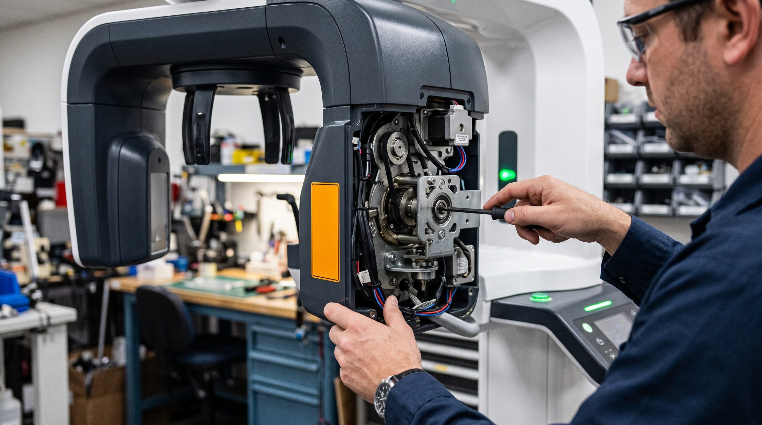
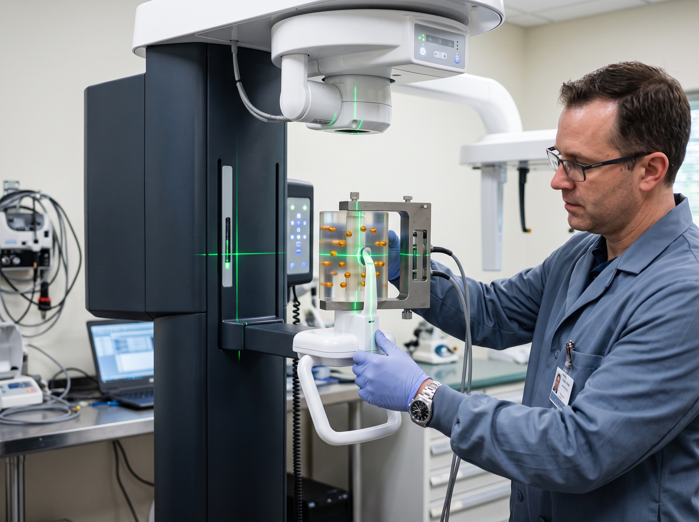
The fastest triage is to run an exposure with the patient out of the equation — a phantom or test object clamped in the head positioner. If a static object still blurs, the fault is in the machine. Watch and listen during a test sweep: a healthy rotation is smooth and near-silent. Hesitation, chatter, a ticking bearing, or visible jerk in the arm all point straight at the mechanism. Check drive-belt tension against the manufacturer spec, spin the arm bearings by hand for roughness or play, and confirm the motor reaches and holds speed.
Bands, Steps, and Density Variation: Usually Mechanical, Sometimes the Detector
Vertical bands, horizontal steps, or a gradient where one part of the image is darker than the rest are among the most frustrating faults, and they almost always come down to a mismatch between motion and readout. The sensor builds the image column by column as the arm moves. If the rotation speed is inconsistent — the arm briefly slows or surges — the columns captured during that interval are stretched or compressed and record a different density, printing as a vertical band or a visible step.
Work the mechanical causes first:
- Drive-belt wear or slip — a glazed, cracked, or loose timing belt lets the arm speed wander, producing irregular banding.
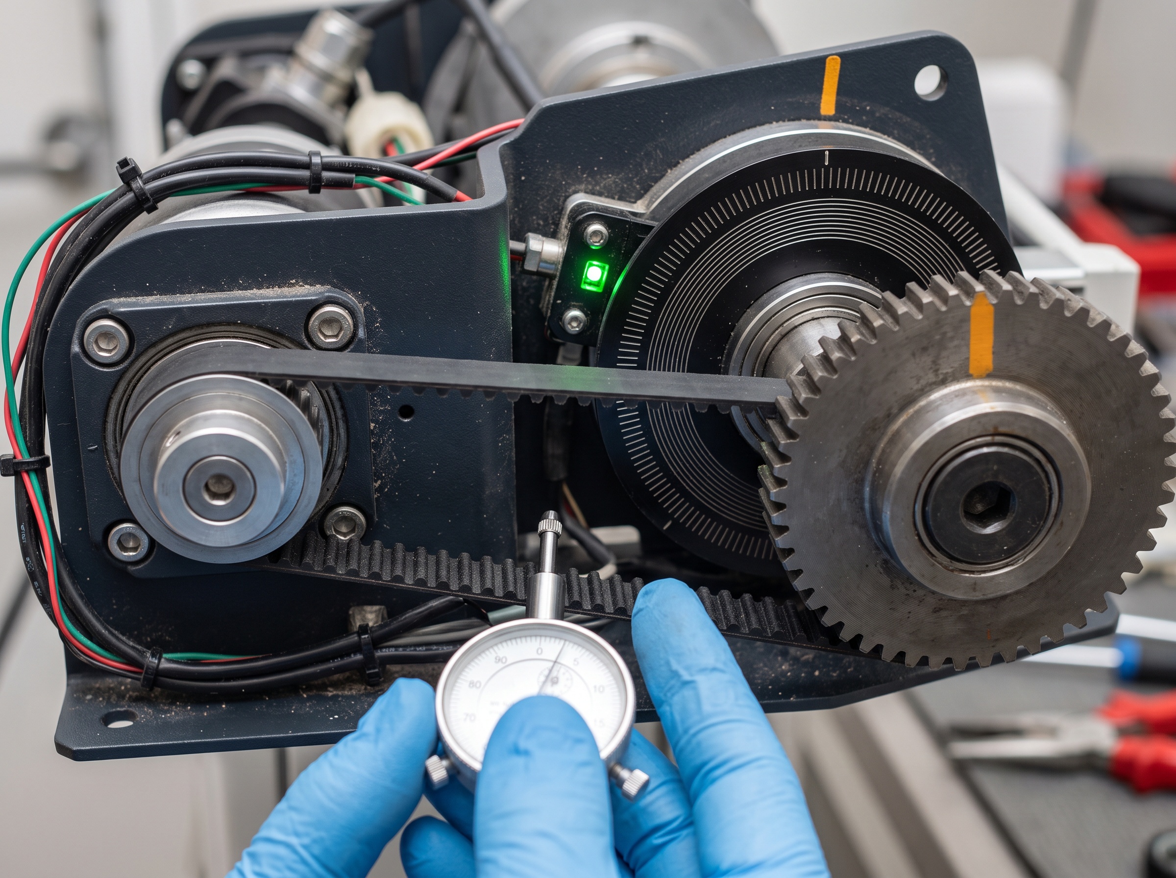
- Motor or encoder faults — the optical encoder tells the controller where the arm is and how fast it is moving. A dirty encoder disc, a failing sensor, or a marginal connection feeds bad position data, and the synchronization between motion and sensor readout breaks down into regular or stepped bands.
- Rotation-speed inconsistency from a worn bearing or binding cable track imposes the same signature.
If the mechanics check out clean, suspect the detector. A dead or drifting line of pixels in the sensor prints as a fixed, perfectly straight band that appears in the same position on every image regardless of rotation — the tell that separates a detector line artifact from a mechanical one. Reseat the sensor data cable, run the detector calibration or flat-field routine, and compare. Mechanical bands move or vary with the sweep; detector bands are frozen in place.
Focal-Trough and Layer Errors: When the Sharp Zone Wanders
When part of the arch is consistently blurred, magnified, or narrowed even with correct positioning, the focal trough itself has moved. The image layer is defined jointly by the mechanical sweep geometry and by where the patient’s anatomy is held — so both the machine and the positioning hardware matter.
Inspect the patient-support chain first: a worn or cracked bite stick, a loose or bent chin rest, or a temple support that no longer clamps repeatably lets the jaw sit forward or back of the trough, mimicking a calibration fault. Replace worn bite pieces on schedule — they are cheap and they drift. If the positioning hardware is sound, the fault is calibration drift in the rotation geometry, confirmed with a test object. A bead or wire phantom placed in the trough should image its reference markers sharp, correctly spaced, and at the specified magnification. If the beads blur or the spacing is wrong, the trough has shifted and the unit needs a geometry/calibration routine — typically a manufacturer service procedure.
A Diagnostic Workflow That Isolates the Cause
Faults overlap, so work them in an order that eliminates whole categories at each step rather than guessing:
- Reproduce it. Get several example images and, if possible, replicate the fault on demand. Intermittent faults are usually mechanical or connector-related.
- Remove the patient. Expose a phantom or test object. If the fault survives without a patient, it is the machine — not positioning or movement.
- Classify the pattern. Magnified upward-sloping duplicate → ghost (benign). Uniform blur → rotation. Localized blur → focal trough. Moving bands → drive/encoder. Fixed straight band → detector.
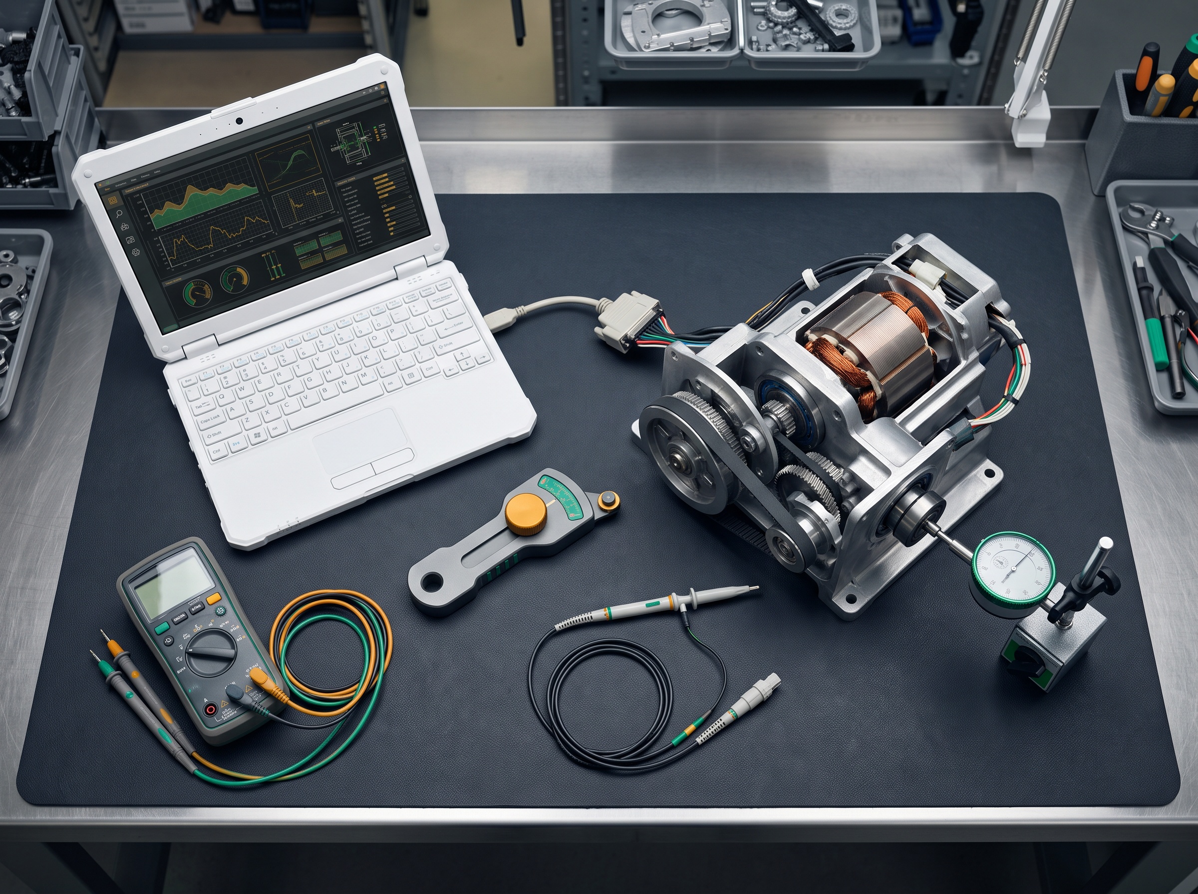
- Inspect the mechanism. Check drive-belt condition and tension, feel the bearings for roughness and play, verify the motor holds speed, and clean and inspect the encoder disc and its wiring.
- Use the service tools. Run the manufacturer’s test mode and diagnostic sweep; many units log rotation-speed, motor-current, and encoder errors that name the fault outright.
- Verify calibration. Confirm focal-trough geometry and detector flat-field with a phantom before you close the panels.
Prevention, Monitoring, and When to Call for Service
Most panoramic image faults are the visible end of a slow mechanical decline, so a modest maintenance rhythm prevents the emergency call. Build a schedule around the moving parts and the geometry:
- Inspect the rotation mechanism, drive belt, and cable track periodically for wear, glazing, cracking, and correct tension.
- Check the arm bearings for roughness, noise, or play, and keep the encoder disc and optics clean.
- Replace bite sticks and inspect the chin rest and temple supports so positioning stays repeatable.
- Run a periodic phantom exposure and detector calibration, and keep dated reference images so density and sharpness drift is caught early.
- Train the clinical staff to remove jewelry and to recognize a benign ghost so those cases are not logged as machine faults.
Know your line. Cleaning an encoder, tensioning or replacing a belt, reseating a data cable, and running standard test modes are routine field work. But focal-trough recalibration, motor or encoder replacement on synchronized drives, sensor replacement, and anything touching X-ray output or dose belongs with a qualified service engineer and manufacturer procedures — with a follow-up performance and dose verification where required. When the pattern points to synchronization or detector internals and the standard checks do not clear it, call for professional service rather than chasing calibration you cannot verify. A panoramic that images a phantom sharp, even, and ghost-free is a machine you can hand back with confidence.