Electrical Voltage Fluctuations in Dental X-Ray Equipment: Comprehensive Troubleshooting and Repair Guide

Voltage fluctuations represent one of the most challenging electrical issues affecting dental X-ray equipment performance. These power variations can cause inconsistent image quality, equipment malfunctions, and potentially expensive component failures. Understanding how to diagnose and resolve voltage-related problems is essential for maintaining reliable radiographic operations.

Understanding Voltage Requirements in Dental X-Ray Systems

Modern dental X-ray equipment typically requires stable single-phase or three-phase power supplies ranging from 208-240 VAC. Line voltage below 208V often necessitates step-up transformers, while voltages exceeding specification can damage sensitive electronic components. The high-voltage generator converts these input voltages to the kilovoltage levels required for X-ray production, making stable input power crucial for consistent performance.

Dental X-ray systems are particularly sensitive to power fluctuations because they rely on precise voltage control for exposure parameter accuracy. When input voltage varies, the resulting kVp and mAs settings can deviate from intended values, directly affecting image quality and patient radiation dose.

Common Voltage Fluctuation Symptoms and Indicators

Digital multimeter measuring voltage on dental X-ray generator panel

Voltage-related issues manifest in various ways that skilled technicians can identify through systematic observation:

  • Inconsistent Image Density: Images appear too light or dark despite consistent exposure settings
  • Exposure Timer Inaccuracy: Actual exposure times deviate from programmed values
  • Generator Error Messages: Control panels display voltage warnings or fault codes
  • Equipment Resets: Spontaneous system shutdowns or parameter resets during operation
  • Tube Heating Issues: Excessive tube temperature warnings or premature tube failure
  • Control Panel Flickering: Display instability or intermittent control responses

These symptoms often correlate with facility electrical issues such as inadequate service capacity, loose connections, or aging transformers. Environmental factors including HVAC load cycling and equipment startup surges can also contribute to voltage instability.

Diagnostic Testing Procedures for Voltage Issues

Effective voltage troubleshooting requires systematic measurement and documentation of electrical parameters. Begin diagnostics with proper safety protocols, ensuring all personnel understand electrical hazards and appropriate protective measures.

Initial Voltage Measurements:

  • Use calibrated digital multimeters with true RMS capability
  • Measure line voltage at the equipment input terminals
  • Record voltage readings during idle, standby, and exposure conditions
  • Document voltage variations over extended monitoring periods

Load Testing Protocol:

  • Monitor voltage stability during maximum exposure settings
  • Test with various tube positions and angulation settings
  • Evaluate voltage drop during concurrent equipment operation
  • Assess power supply recovery time following exposure cycles

Advanced diagnostics may require oscilloscope analysis to identify voltage waveform distortion, harmonic content, or transient spikes that can affect equipment operation. Power quality analyzers provide comprehensive data on voltage stability, frequency variations, and power factor measurements.

Generator and Power Supply Component Troubleshooting

Internal power supply components and transformers in dental X-ray equipment

Internal power supply components require methodical testing to isolate voltage-related failures. High-voltage generators contain multiple transformer stages, rectifier circuits, and regulation systems that can contribute to voltage instability.

Transformer Testing:

  • Verify primary winding continuity and insulation resistance
  • Test turns ratio accuracy across all voltage taps
  • Check for overheating, discoloration, or oil leakage
  • Measure no-load and full-load voltage regulation

Rectifier Circuit Analysis:

  • Test high-voltage rectifier diodes for forward and reverse characteristics
  • Evaluate filter capacitor condition and ripple voltage levels
  • Verify voltage regulation circuit operation and feedback systems
  • Check for component aging or thermal stress indicators

Many modern systems incorporate voltage compensation circuits that automatically adjust for input variations. These systems require calibration verification and may need reprogramming following component replacement or facility electrical modifications.

Facility Electrical System Evaluation

Comprehensive voltage troubleshooting extends beyond the X-ray equipment to include facility electrical infrastructure assessment. Poor building electrical systems often contribute to equipment voltage problems.

Service Panel Inspection:

  • Verify adequate service capacity for total facility electrical load
  • Inspect panel connections for looseness, corrosion, or overheating
  • Check circuit breaker condition and proper sizing
  • Evaluate grounding system integrity and resistance measurements

Wiring and Distribution Assessment:

  • Test conductor resistance and voltage drop calculations
  • Verify proper circuit sizing for equipment amperage requirements
  • Check for aluminum wiring or obsolete installation methods
  • Evaluate dedicated circuit requirements and isolation needs

Aging facilities may require electrical system upgrades to support modern digital X-ray equipment. Consultation with qualified electrical contractors ensures compliance with current codes and optimal equipment performance.

Repair Solutions and Voltage Stabilization Methods

Effective voltage problem resolution often requires multiple approaches depending on root cause identification. Solutions range from simple adjustments to comprehensive system upgrades.

Equipment-Level Solutions:

  • Voltage regulator installation for input power conditioning
  • UPS systems with voltage regulation and surge protection
  • Transformer tap adjustment for voltage optimization
  • Component replacement for failed regulation circuits

Facility-Level Improvements:

  • Dedicated circuit installation for X-ray equipment isolation
  • Service panel upgrades for increased capacity and reliability
  • Power factor correction to improve electrical efficiency
  • Surge suppression systems for transient protection

Preventive maintenance programs should include regular voltage monitoring, connection tightening, and electrical system inspection. Documentation of voltage trends helps identify developing problems before equipment failure occurs.

Prevention and Monitoring Strategies

Long-term voltage stability requires ongoing monitoring and proactive maintenance approaches. Establishing baseline measurements allows early detection of deteriorating conditions.

Install permanent voltage monitoring systems where chronic problems exist. These systems provide continuous data logging and alarm capabilities for immediate problem notification. Regular calibration ensures measurement accuracy and reliability.

Staff training on voltage-related symptoms empowers operators to recognize developing problems and request service before complete failures occur. Comprehensive documentation of electrical issues supports warranty claims and helps identify recurring problems requiring systematic resolution.

Coordination with facility maintenance teams ensures electrical system changes consider X-ray equipment requirements. Planned electrical work should include voltage impact assessment and equipment protection measures.

Dental X-Ray Tube Aging and Performance Degradation: Diagnostic Testing and Replacement Criteria

Dental X-ray tubes are critical components that gradually degrade over time, affecting image quality and exposure consistency. Understanding the signs of tube aging and implementing proper diagnostic testing protocols ensures optimal radiographic performance and prevents unexpected equipment failures.

Understanding X-Ray Tube Aging Mechanisms

X-ray tube deterioration occurs through several distinct mechanisms that impact both the cathode filament and tungsten anode target. The primary aging factors include:

  • Tungsten evaporation – High-temperature operation causes tungsten atoms to migrate from the anode target, gradually reducing output efficiency
  • Filament degradation – Repeated heating cycles cause cathode filament thinning and eventual burnout
  • Anode pitting – Electron bombardment creates microscopic craters on the tungsten target surface
  • Glass envelope deposits – Evaporated tungsten creates a metallic film on the tube housing interior

These degradation processes typically manifest after 50,000 to 100,000 exposures, depending on usage patterns and maintenance protocols.

Digital diagnostic display showing X-ray exposure parameters

Performance Testing and Diagnostic Procedures

Regular performance monitoring identifies tube degradation before it affects clinical operations. Essential diagnostic tests include:

kVp Output Verification

Use calibrated kVp meters to measure actual output against control panel settings. Variations exceeding ±5% indicate potential tube aging or high-voltage generator issues. Document readings monthly and track trends over time.

Exposure Time Accuracy Testing

Verify exposure timer accuracy using digital timing devices. Aging tubes often require longer exposure times to achieve consistent density, indicating reduced output efficiency.

Half-Value Layer (HVL) Measurement

HVL testing determines beam quality and filtration effectiveness. Decreasing HVL values may indicate tungsten target deterioration or improper filtration.

Service technician performing X-ray tube diagnostics

Replacement Decision Criteria

Multiple factors determine when X-ray tube replacement becomes necessary:

  • Output decline – Greater than 20% reduction from baseline measurements
  • Exposure consistency – Variations exceeding 10% between identical settings
  • Image quality degradation – Increased noise, reduced contrast, or artifacts
  • Safety compliance – Failure to meet regulatory radiation output requirements

Cost-Benefit Analysis

Consider replacement when repair costs exceed 60% of new tube value, or when productivity losses from inconsistent performance impact patient throughput.

Extending Tube Life Through Proper Operation

Implement these practices to maximize tube longevity:

  • Warm-up procedures – Allow proper filament heating before high-demand exposures
  • Exposure optimization – Use lowest practical kVp and mAs settings for adequate image quality
  • Cooling periods – Avoid rapid successive exposures that exceed anode heat capacity
  • Environmental control – Maintain stable temperature and humidity in equipment rooms

Regular maintenance scheduling and performance documentation ensure optimal equipment utilization while maintaining consistent radiographic quality throughout the tube’s operational life.

Dental X-Ray Collimator Alignment and PID Positioning: Complete Troubleshooting Guide for Service Technicians

Proper collimator alignment and Position Indicating Device (PID) positioning are critical components of dental X-ray equipment functionality. Misalignment issues can result in cone cuts, inadequate coverage, and repeated exposures that compromise both image quality and radiation safety protocols.

Understanding Collimator Function and Common Misalignment Issues

The collimator assembly controls X-ray beam size and shape, working in conjunction with the PID to ensure proper alignment with the receptor. When these components aren’t properly aligned, several characteristic artifacts appear in radiographic images.

Technical diagram showing PID collimator misalignment examples

Common alignment issues include angular misalignment between the PID and collimator housing, mechanical wear in positioning joints, and calibration drift in automated positioning systems. These problems manifest as cone cuts where portions of the receptor remain unexposed, creating characteristic crescent-shaped clear areas on the image.

Diagnostic Procedures for Collimator Alignment

Service technicians should begin troubleshooting with a systematic visual inspection of the collimator assembly. Check for loose mounting hardware, worn pivot joints, and damaged alignment indicators. The PID must maintain flush contact with the collimator housing throughout the full range of motion.

Use alignment test tools to verify beam centering accuracy. Position a test receptor and alignment device, ensuring the PID is flush against the alignment ring. Any gaps or angular discrepancies indicate mechanical adjustment requirements.

Testing Beam Coverage and Centering

Perform test exposures using standardized positioning aids to verify beam coverage matches receptor dimensions. Proper alignment should provide complete receptor coverage with minimal beam overlap beyond the receptor edges. Document any coverage deficiencies with measurements and photographic evidence.

Mechanical Adjustment and Calibration Procedures

Most collimator alignment corrections require mechanical adjustment of mounting hardware and positioning mechanisms. Begin with the primary mounting assembly, checking torque specifications on all fasteners and adjusting as necessary.

Dental technician performing collimator alignment service

For systems with automated positioning, recalibrate the positioning sensors and verify proper communication between the control system and positioning motors. Document all adjustment values and test results according to manufacturer specifications.

PID Alignment Verification

After mechanical adjustments, verify PID alignment using precision measurement tools. The PID cone must maintain parallel alignment with the receptor plane throughout the adjustment range. Angular deviations exceeding 2 degrees typically require additional mechanical correction.

Test the full range of motion, ensuring smooth operation without binding or excessive play in positioning joints. Replace worn components as identified during testing procedures.

Quality Assurance and Final Testing

Complete alignment verification requires comprehensive testing using standardized phantoms and exposure protocols. Perform multiple exposures at different positioning angles, documenting beam coverage consistency and image quality parameters.

Verify that automatic exposure control systems properly compensate for positioning variations. Record exposure timing accuracy and consistency across the full range of positioning options.

Documentation and Service Records

Maintain detailed service records documenting all alignment measurements, adjustment procedures, and final verification results. Include before and after test images showing alignment improvements and compliance with manufacturer specifications.

Provide the customer with calibration certificates and recommended maintenance schedules to prevent future alignment issues. Schedule follow-up inspections according to regulatory requirements and manufacturer recommendations.

Bite Block Positioning Techniques and Patient Comfort in Dental Radiography: Essential Best Practices Guide

Proper bite block positioning is fundamental to obtaining high-quality dental radiographs while ensuring maximum patient comfort. Modern radiographic positioning techniques focus on ergonomic design and patient-centered approaches that reduce anxiety and improve diagnostic outcomes.

Understanding Bite Block Technology and Design

Contemporary bite blocks feature rounded edges and reduced thickness specifically engineered to enhance patient comfort during radiographic procedures. The color-coded system (typically blue for anterior, yellow for posterior, and red for bitewing) allows for quick identification and proper alignment, significantly reducing positioning errors and retakes.

Ergonomic dental bite blocks with rounded edges in different colors designed for patient comfort

The open bite block design provides a softer bite experience while maintaining receptor stability. This approach is particularly beneficial for patients with limited mouth opening or those who experience discomfort with traditional positioning devices.

Optimal Positioning Techniques for Patient Comfort

The preferred positioning method involves placing the bite block and receptor in the correct position first, then having the patient slowly bite to maintain placement. This technique prevents the common error of having patients bite the receptor into place, which often leads to positioning mistakes and patient discomfort.

Key Positioning Principles

  • Position the receptor more lingually where the palate and floor are deeper for easier placement
  • Ensure the receptor remains perpendicular to the occlusal plane to prevent image distortion
  • Allow patients to control the biting pressure rather than forcing the position
  • Use gentle, guided movements to achieve optimal alignment

Advanced Techniques for Special Patient Populations

Special considerations apply to different patient groups, particularly those with anatomical variations or physical limitations. For edentulous patients requiring panoramic radiographs, specialized bite blocks with enhanced stability features provide better bilateral symmetry and reduced patient movement during exposure.

Dental hygienist demonstrating proper bite block positioning technique with a patient in a dental chair

The Frankfort horizontal plane alignment is critical for panoramic positioning, and specialized bite blocks help maintain proper head position throughout the exposure cycle. These devices reduce common positioning errors that can compromise image quality and require retakes.

Comfort Enhancement Strategies

Modern positioning systems incorporate several comfort-enhancing features:

  • Lightweight construction to reduce fatigue during longer procedures
  • Smooth, rounded surfaces that eliminate pressure points
  • Ergonomic shapes that conform to natural oral anatomy
  • Quick assembly systems that minimize chair time

Quality Assurance and Error Prevention

Proper bite block positioning directly impacts image quality and diagnostic value. The extension cone paralleling technique, when combined with appropriate bite block selection, ensures distortion-free radiographs and prevents cone cutting artifacts that necessitate retakes.

Common Positioning Errors to Avoid

  • Placing the bite block on opposing teeth instead of supporting the receptor
  • Allowing excessive receptor movement during exposure
  • Improper angulation due to inadequate bite block support
  • Rushing the positioning process and causing patient discomfort

Maintenance and Sterilization Protocols

Bite blocks require proper maintenance to ensure patient safety and equipment longevity. Autoclavable bite blocks offer cost-effective sterilization and can withstand repeated use while maintaining their structural integrity and comfort features.

Regular inspection for wear, cracks, or sharp edges is essential to maintain patient comfort and prevent potential injuries. Replace damaged components immediately to ensure consistent performance and patient safety.

Future Developments in Positioning Technology

Emerging technologies continue to improve bite block design and positioning accuracy. Digital integration features allow for better workflow coordination between positioning devices and imaging software, while enhanced ergonomic designs focus on reducing patient stress and improving overall experience.

The evolution toward patient-centered radiographic procedures emphasizes the importance of proper positioning technique training and equipment selection. Investing in quality positioning systems with comfort-focused features ultimately benefits both patients and practitioners through improved image quality and reduced procedural time.

Panoramic X-Ray Positioning Errors: Common Patient Placement Issues and Troubleshooting Solutions

Panoramic radiography is one of the most commonly performed imaging procedures in dental practice, providing a comprehensive view of the oral and maxillofacial structures in a single image. However, patient positioning errors represent the leading cause of diagnostically inadequate panoramic radiographs, resulting in retakes that expose patients to unnecessary radiation and reduce clinical efficiency.

Understanding and preventing these positioning errors is crucial for dental professionals to ensure optimal image quality while minimizing patient exposure. This comprehensive guide examines the most frequent positioning mistakes and provides practical troubleshooting solutions for each scenario.

Understanding the Focal Trough Concept

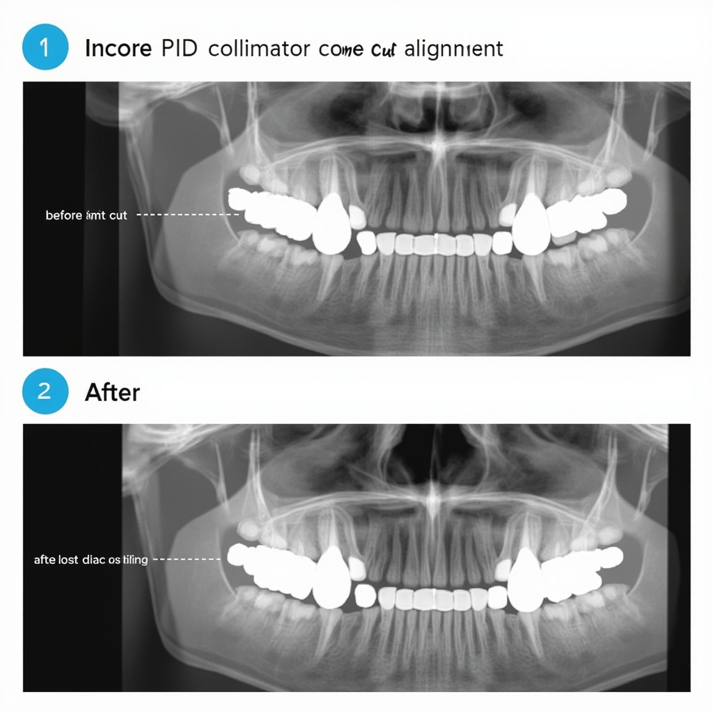
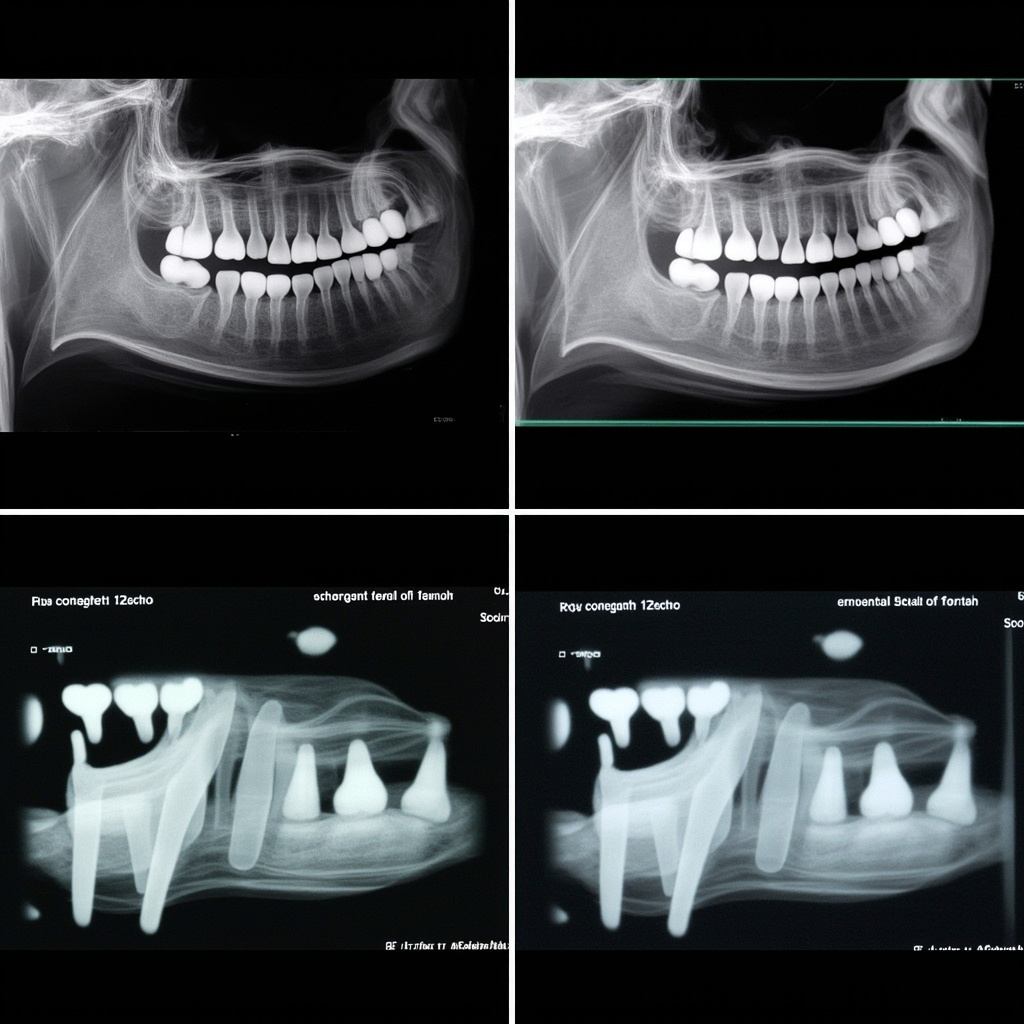
The focal trough is a three-dimensional curved zone where structures appear sharp and properly sized in the panoramic image. Patient positioning errors typically result from improper placement relative to this focal trough, causing various artifacts and diagnostic challenges.

When patients are positioned correctly within the focal trough, the anterior teeth appear normal in size and sharpness. However, deviations from proper positioning create predictable patterns of image distortion that can be identified and corrected.

Dental technician positioning patient for panoramic X-ray

Most Common Positioning Errors

Chin Position Problems

Chin Tipped Too High: When the patient’s chin is positioned too high, the hard palate appears as a large radiopaque band across the maxillary teeth, obscuring the apical regions. The mandibular anterior teeth may appear elongated and blurred. This error occurs when the Frankfort horizontal plane isn’t parallel to the floor.

Chin Tipped Too Low: An excessively low chin position causes the mandibular symphysis to appear as a dense radiopaque shadow over the lower anterior teeth. The cervical spine may also superimpose over the ramus area, reducing diagnostic value.

Anterior-Posterior Positioning Issues

Patient Too Far Forward: When patients are positioned anterior to the focal trough, the anterior teeth appear narrow and blurred. The premolars may overlap, and overall magnification is reduced. This commonly occurs when patients aren’t properly guided to the bite block.

Patient Too Far Backward: Posterior positioning makes the anterior teeth appear wide and magnified with reduced sharpness. The maxillary and mandibular anterior teeth may not overlap properly, creating gaps in the arch continuity.

Tongue Positioning Failures

The most frequent error in panoramic imaging is failure to position the tongue against the hard palate. When the tongue isn’t properly positioned, a large radiolucent area appears over the maxillary teeth, obscuring root structures and making periapical assessment impossible.

This error significantly impacts diagnostic quality because the air space created by improper tongue placement mimics pathology and can mask actual dental conditions.

Patient Movement and Stability Issues

Patient movement during the 12-20 second exposure time creates characteristic horizontal streaking artifacts across the image. Modern panoramic units with shorter exposure times have reduced this problem, but patient coaching remains essential.

Comparison of correct versus incorrect panoramic X-ray positioning results

Troubleshooting and Prevention Strategies

Pre-Exposure Patient Preparation

Clear Instructions: Provide step-by-step verbal guidance about proper positioning. Explain the importance of remaining still and maintaining tongue position throughout the exposure.

Physical Positioning Aids: Use bite blocks, chin rests, and head restraints properly. Ensure the bite block groove aligns with the patient’s anterior teeth and that lateral head supports are snug but comfortable.

Breathing Instructions: Instruct patients to breathe normally through their nose and swallow once before beginning the exposure to ensure proper tongue position.

Operator Techniques

Visual Alignment Checks: Verify that the midsagittal plane is perpendicular to the floor and the Frankfort horizontal plane is parallel to the floor. Use the machine’s alignment lights to confirm proper positioning.

Height Adjustments: Ensure the patient’s height places the occlusal plane at the appropriate level for the specific panoramic unit. Most manufacturers provide height guidelines based on patient measurements.

Stability Monitoring: Watch for patient movement during positioning and provide additional support or instruction as needed. Consider using foam blocks or additional stabilization for anxious patients.

Quality Control Measures

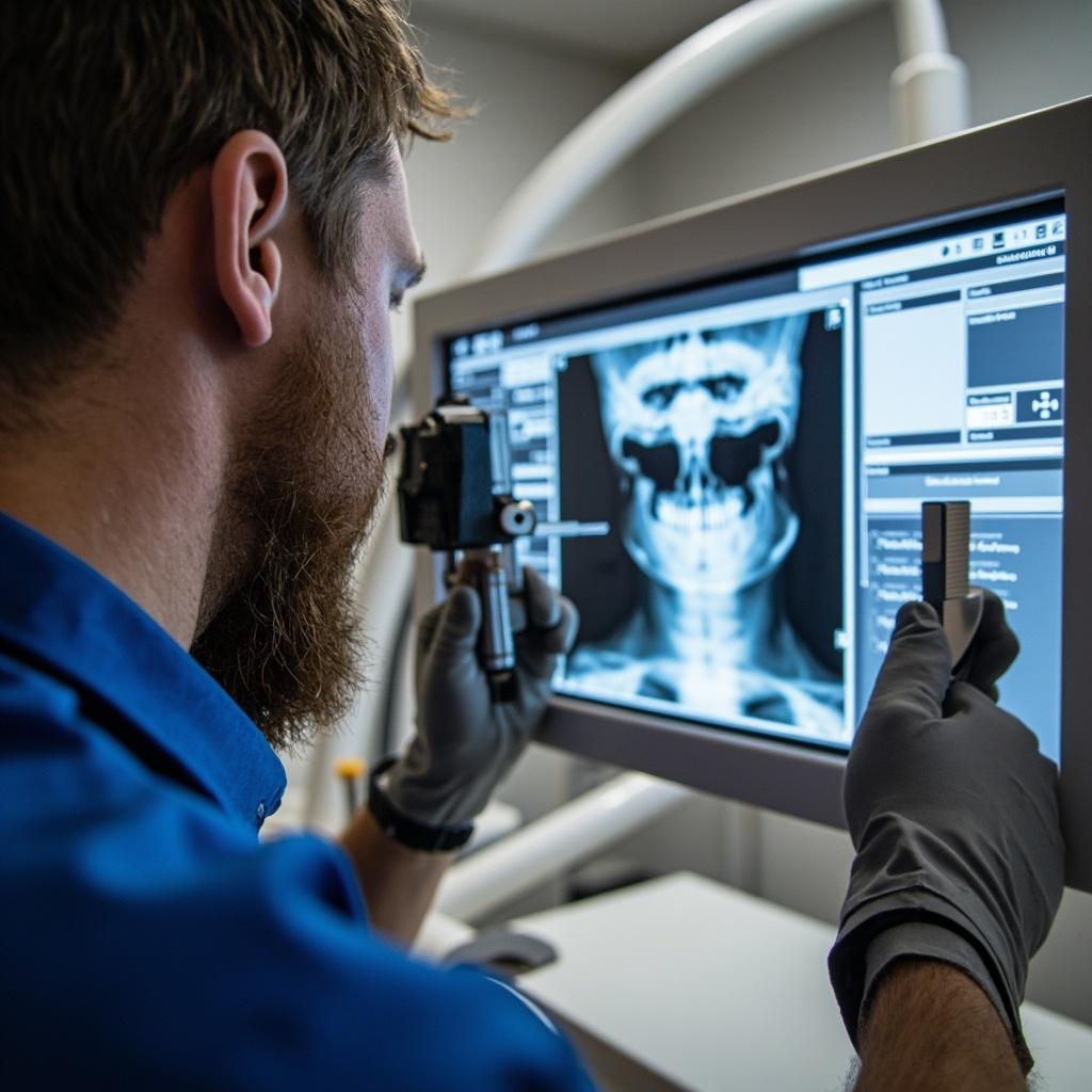
Immediate Image Review: Examine each image immediately after exposure to identify positioning errors. This allows for immediate retakes when necessary and provides learning opportunities.

Error Pattern Documentation: Keep records of common positioning errors to identify operator training needs and equipment calibration issues.

Regular Calibration: Ensure panoramic equipment alignment lights and positioning guides are properly calibrated according to manufacturer specifications.

Specific Correction Techniques

For Chin Position Errors

Use the Frankfort horizontal plane (imaginary line from the ear canal to the lower border of the orbit) as your primary reference. This line should be parallel to the floor. Adjust the chin rest height and angle to achieve proper alignment.

For Anterior-Posterior Positioning

The bite block groove should align with the patient’s incisal edges. Use gentle but firm guidance to ensure proper anterior tooth placement. For patients with missing anterior teeth, use alternative positioning references such as the canines.

For Tongue Position

Demonstrate proper tongue placement by asking the patient to make a ‘clicking’ sound with their tongue, then instruct them to keep their tongue in that raised position. Have patients practice this before beginning the exposure.

Managing Difficult Cases

Certain patient populations require modified positioning techniques:

Pediatric Patients: Use shorter exposure times when available and provide clear, age-appropriate instructions. Consider parental assistance for very young children.

Patients with Limited Mobility: Wheelchair-accessible panoramic units or modified positioning techniques may be necessary. Ensure adequate support while maintaining proper alignment.

Patients with TMJ Disorders: Be aware that jaw opening limitations may affect bite block placement. Use the smallest comfortable bite block and consider alternative positioning aids.

Cost and Efficiency Considerations

Positioning errors directly impact practice efficiency and patient care costs. Retakes due to positioning errors:

  • Double radiation exposure for patients
  • Reduce appointment efficiency
  • Increase operator workload
  • Delay diagnosis and treatment
  • Impact patient confidence in the practice

Investing time in proper positioning technique training and equipment calibration pays dividends in improved image quality and reduced retake rates.

Conclusion

Panoramic positioning errors are largely preventable through proper training, consistent technique, and attention to detail. By understanding the relationship between patient position and image quality, dental professionals can significantly improve their diagnostic imaging outcomes.

Regular review of positioning techniques, ongoing staff training, and systematic quality control measures ensure optimal panoramic radiographic results. Remember that proper positioning is not just about image quality—it’s about providing the best possible patient care while minimizing radiation exposure.

The key to successful panoramic imaging lies in consistent application of positioning principles, clear patient communication, and immediate quality assessment of each image. With these fundamentals in place, positioning errors become rare occurrences rather than routine challenges.

UPS Backup Power Systems for Dental X-ray Equipment: Installation and Troubleshooting Guide

Uninterruptible Power Supply (UPS) systems are critical infrastructure components for dental offices that rely on digital X-ray equipment. Power interruptions during imaging procedures can corrupt files, damage sensitive electronics, and compromise patient care workflows. This comprehensive guide covers UPS selection, installation, and troubleshooting specifically for dental X-ray applications.

Understanding UPS Requirements for Dental X-ray Equipment

Digital X-ray systems require stable, clean power to function properly. Unlike traditional office computers, dental imaging equipment has specific power quality requirements that standard backup systems cannot meet. Power disruptions during image capture frequently result in corrupted files, forcing costly reshoot procedures and extending patient appointment times.

Medical-grade UPS systems differ from consumer units in several critical ways. They provide faster switching times (less than 4 milliseconds), superior voltage regulation, and extended runtime capabilities. These features are essential for protecting expensive X-ray sensors, preventing data loss during network transfers, and maintaining DICOM compliance standards.

Modern dental X-ray equipment typically consumes between 500-2000 watts during operation, with peak power demands occurring during tube warmup sequences. UPS systems must be sized to handle these power spikes while providing adequate runtime for safe system shutdown procedures.

UPS Selection and Sizing Guidelines

Selecting the appropriate UPS capacity requires careful analysis of your X-ray equipment’s power consumption patterns. Start by documenting the nameplate ratings for all connected devices: X-ray generator, digital sensors, computer workstations, monitors, and network equipment.

Close-up of UPS control panel with digital display showing power status and battery indicators

Load calculations should include a 25-30% safety margin above actual consumption to accommodate equipment aging and future upgrades. For typical dental installations, a 3000-5000 VA UPS provides adequate protection for a single X-ray room, while larger practices may require 8000-10000 VA systems for multiple rooms.

Runtime requirements vary based on your backup strategy. If automatic shutdown procedures are implemented, 10-15 minutes of runtime suffices. However, practices requiring continued operation during brief outages should consider extended battery configurations providing 30-60 minutes of protection.

Battery technology selection impacts both performance and maintenance requirements. Sealed lead-acid batteries are cost-effective but require replacement every 3-4 years. Lithium-ion alternatives offer longer service life and smaller footprints but involve higher initial costs.

Installation Best Practices and Wiring Requirements

Proper UPS installation begins with electrical infrastructure assessment. Dedicated circuits are recommended for X-ray equipment to minimize interference from other office loads. Ground fault circuit interrupters (GFCI) should not be used on UPS-protected circuits, as they may cause nuisance tripping during power transfer events.

Technical diagram showing UPS electrical connections for dental X-ray equipment installation

UPS units should be installed in climate-controlled environments away from direct sunlight and heat sources. Adequate ventilation is critical for battery longevity, with temperature increases above 25°C significantly reducing service life. Wall-mounting options help conserve floor space while ensuring proper airflow around cooling vents.

Grounding connections require special attention in medical environments. The UPS must be connected to the equipment grounding conductor, and isolated grounding systems should be evaluated by qualified electrical contractors to ensure compliance with NEC Article 517 requirements for patient care areas.

Network connectivity enables remote monitoring and automated shutdown capabilities. SNMP cards or USB connections allow practice management systems to receive power failure notifications and initiate graceful shutdown procedures before battery depletion.

Common UPS Problems and Troubleshooting Procedures

Battery failure represents the most frequent UPS issue in dental offices. Symptoms include reduced runtime, frequent low-battery alarms, and failure to transfer to battery power during outages. Battery testing should be performed annually, with replacement typically required every 3-5 years depending on usage patterns and environmental conditions.

Overload conditions occur when connected equipment exceeds UPS capacity. Digital X-ray systems may develop higher power consumption over time due to aging components or software updates. Regular load monitoring helps identify gradual increases before they cause protection failures.

Input voltage problems can trigger unnecessary battery mode operation, reducing battery life and generating nuisance alarms. Voltage logging helps identify utility power quality issues that may require additional conditioning or utility company consultation.

Communication failures between UPS and connected systems prevent proper shutdown procedures during extended outages. Regular testing of network monitoring software and backup communication methods ensures reliable operation when primary power fails.

Maintenance Schedules and Performance Testing

Preventive maintenance extends UPS service life and ensures reliable protection when needed. Monthly visual inspections should verify proper ventilation, check for loose connections, and confirm status indicator functionality. Battery voltage measurements help identify failing cells before complete failure occurs.

Annual performance testing validates UPS capacity and transfer timing under controlled conditions. These tests should be scheduled during non-patient hours and coordinated with X-ray equipment manufacturers to avoid warranty issues.

Battery replacement intervals depend on environmental conditions and discharge cycling frequency. High-temperature environments accelerate battery aging, while frequent power outages increase cycle stress. Maintaining detailed maintenance logs helps optimize replacement timing and identify potential system issues.

Firmware updates for UPS systems should be evaluated carefully, as they may affect compatibility with existing monitoring software or change operational parameters. Always verify compatibility with X-ray equipment manufacturers before implementing updates in clinical environments.

Digital X-Ray Sensor Connection and Communication Failures: USB, Ethernet, and Wireless Troubleshooting Guide

Digital X-ray sensors rely on stable connections to transmit image data from the sensor to the computer system. Connection and communication failures can disrupt dental workflow and prevent proper image acquisition. This comprehensive guide addresses common sensor connectivity issues and provides systematic troubleshooting approaches for USB, Ethernet, and wireless connections.

Understanding Digital Sensor Communication

Modern dental X-ray sensors use various communication protocols to transmit captured images to the imaging software. The most common connection types include:

  • USB connections: Direct wired connection for immediate image transfer
  • Ethernet networking: Network-based communication for distributed systems
  • Wireless protocols: Wi-Fi or proprietary wireless for untethered operation

Each connection type has unique failure modes and troubleshooting requirements that dental professionals must understand to maintain optimal system performance.

USB Connection Troubleshooting

USB connectivity issues are among the most common sensor problems. These failures often manifest as sensor not being detected, intermittent connections, or failed image transfers.

USB connection troubleshooting diagram

Common USB Issues and Solutions

Sensor Not Detected:

  • Check USB cable connections at both sensor and computer ends
  • Test with a different USB port, preferably USB 2.0 for older sensors
  • Verify cable integrity by testing with a known working sensor
  • Restart the imaging software and allow time for sensor recognition

Intermittent Connection Loss:

  • Examine cable for kinks, bends, or damage near connectors
  • Check USB port for loose connections or debris
  • Disable USB power management in Windows Device Manager
  • Update USB drivers and sensor software to latest versions

Failed Image Transfers:

  • Monitor system resources – insufficient memory can cause transfer failures
  • Close unnecessary applications to free system bandwidth
  • Check for Windows updates that might affect USB subsystem
  • Test sensor on a different computer to isolate hardware issues

Network and Ethernet Connectivity Issues

Networked X-ray systems require proper network configuration and stable Ethernet connections. Network issues can prevent sensor communication and image storage to central servers.

Network configuration troubleshooting

Network Troubleshooting Steps

IP Address Configuration:

  • Verify sensor has correct static IP address or DHCP assignment
  • Check subnet mask and gateway settings match network requirements
  • Test connectivity with ping commands to sensor IP address
  • Ensure no IP conflicts exist on the network

Network Infrastructure:

  • Test Ethernet cable with cable tester or known working device
  • Check switch port status and LED indicators
  • Verify network switch or router isn’t dropping connections
  • Monitor network traffic for congestion or bandwidth issues

Firewall and Security:

  • Configure Windows Firewall exceptions for imaging software
  • Check antivirus software isn’t blocking sensor communication
  • Verify network security settings allow sensor traffic
  • Test with temporarily disabled security software to isolate issues

Wireless Sensor Connectivity

Wireless X-ray sensors offer mobility but introduce additional complexity. Wireless failures can stem from signal interference, authentication issues, or power management problems.

Wireless Troubleshooting Protocol

Signal Quality Assessment:

  • Check Wi-Fi signal strength at sensor location
  • Identify potential interference from other devices
  • Test different wireless channels to avoid congestion
  • Position access point for optimal coverage in operatory

Authentication and Security:

  • Verify correct WPA/WPA2 passphrase entry
  • Check MAC address filtering settings on access point
  • Ensure sensor certificate is valid and trusted
  • Test with open network to isolate security issues

Power and Battery Management:

  • Monitor sensor battery levels and charging status
  • Check power saving modes aren’t interfering with connectivity
  • Verify charging dock connections and power supply
  • Test sensor performance during different charge levels

Advanced Diagnostic Techniques

When basic troubleshooting fails, advanced diagnostic methods can identify complex connectivity issues:

Software Diagnostics

Use built-in diagnostic tools within the imaging software to test sensor communication. Most professional systems include connection testing utilities that can identify specific failure points.

System Log Analysis

Review Windows Event Logs for USB, network, or device driver errors that correlate with sensor failures. Look for error codes that can guide specific troubleshooting approaches.

Network Packet Analysis

For networked systems, use network monitoring tools to capture and analyze communication between sensors and imaging computers. This can reveal timeout issues, protocol errors, or bandwidth limitations.

Preventive Maintenance

Regular maintenance prevents many connectivity issues:

  • Monthly inspection of all cables and connectors
  • Quarterly network configuration backup and verification
  • Annual sensor firmware and driver updates
  • Documentation of network settings and troubleshooting history

When to Contact Technical Support

Contact manufacturer support when:

  • Hardware diagnostics indicate sensor failure
  • Multiple troubleshooting approaches have failed
  • Intermittent issues persist despite systematic testing
  • Firmware updates are required but not available publicly

Maintaining reliable digital X-ray sensor connectivity requires systematic troubleshooting approaches and regular preventive maintenance. By understanding common failure modes and implementing proper diagnostic procedures, dental practices can minimize disruption and ensure consistent image acquisition capabilities.

DICOM Network Integration Issues in Dental X-Ray Systems: Troubleshooting Connection and Communication Problems

DICOM (Digital Imaging and Communications in Medicine) network integration is crucial for modern dental practices, enabling seamless communication between digital X-ray equipment and Practice Management Systems (PMS) or PACS (Picture Archiving and Communication System) servers. When DICOM connectivity fails, it disrupts workflow efficiency and can prevent proper image archiving and retrieval.

Understanding DICOM Network Architecture

DICOM networking relies on three fundamental components that must be correctly configured for successful communication:

  • IP Address: The network location of each device
  • Port Number: The communication endpoint (typically 104 or 106)
  • Application Entity (AE) Title: A unique identifier for each DICOM device

These parameters must match exactly between the sending device (X-ray equipment) and receiving device (PACS server or workstation).

DICOM troubleshooting interface showing network diagnostics

Common DICOM Connectivity Problems

Network Layer Issues

The most frequent connectivity problems occur at the network infrastructure level:

  • Firewall Blocking: Corporate firewalls often block non-standard ports used by DICOM communication
  • Network Segmentation: X-ray equipment and PACS servers on different network subnets can’t communicate
  • IP Address Conflicts: Multiple devices assigned the same IP address cause intermittent connectivity
  • DNS Resolution Failures: Using hostnames instead of IP addresses when DNS isn’t properly configured

Configuration Mismatches

Even when network connectivity exists, configuration errors prevent successful DICOM handshakes:

  • Incorrect AE Titles: Case-sensitive AE titles must match exactly between devices
  • Port Number Mismatches: Default DICOM port 104 may be changed to 106 or custom ports
  • Transfer Syntax Issues: Incompatible image compression or transfer protocols
  • Timeout Settings: Network timeouts too short for large image transfers

Systematic Troubleshooting Approach

Step 1: Network Connectivity Testing

Begin troubleshooting with basic network connectivity tests:

  • Ping Test: Verify IP-level connectivity between X-ray equipment and PACS server
  • Telnet Port Test: Test specific DICOM port connectivity (e.g., telnet 192.168.1.100 104)
  • Network Trace: Use packet capture tools to analyze DICOM communication attempts

Step 2: DICOM Configuration Verification

Systematically verify all DICOM parameters:

  • Compare AE titles on both sending and receiving devices
  • Confirm port numbers match exactly
  • Verify IP addresses are correct and reachable
  • Check transfer syntax compatibility

DICOM configuration panel on dental X-ray equipment

Step 3: Advanced Diagnostics

For persistent issues, employ advanced diagnostic techniques:

  • DICOM Echo Testing: Use C-ECHO commands to test basic DICOM connectivity
  • Log File Analysis: Review DICOM service logs for specific error messages
  • Protocol Analysis: Capture and analyze DICOM protocol exchanges using specialized tools

Specific Troubleshooting Scenarios

Intermittent Connection Failures

When DICOM connections work sometimes but fail unpredictably:

  • Check for IP address conflicts on the network
  • Verify network switch port configuration and duplex settings
  • Monitor network utilization during peak usage periods
  • Review DHCP lease times and IP address stability

Image Transfer Timeouts

Large image files may fail to transfer within default timeout periods:

  • Increase network timeout values in DICOM configuration
  • Optimize network bandwidth allocation
  • Consider image compression settings to reduce file sizes
  • Verify network hardware can handle sustained data transfers

Authentication and Security Issues

Modern PACS systems may implement additional security layers:

  • Verify TLS/SSL certificate validity for secure DICOM connections
  • Check user authentication credentials
  • Review access control lists (ACLs) on PACS servers
  • Confirm compliance with security policies

Prevention and Maintenance

Regular System Monitoring

Implement proactive monitoring to prevent connectivity issues:

  • Automated Testing: Schedule regular DICOM echo tests to verify connectivity
  • Log Monitoring: Set up alerts for DICOM communication errors
  • Performance Tracking: Monitor transfer times and success rates
  • Network Health Checks: Regular verification of network infrastructure

Documentation and Change Management

Maintain comprehensive documentation of your DICOM network configuration:

  • IP address assignments and DHCP reservations
  • AE title registry for all DICOM devices
  • Port number assignments and firewall rules
  • Configuration backup procedures

Advanced Solutions

DICOM Routers and Gateways

For complex network environments, DICOM routers provide enhanced connectivity:

  • Protocol translation between different DICOM implementations
  • Load balancing across multiple PACS servers
  • Enhanced security and audit logging
  • Centralized configuration management

Cloud-Based PACS Integration

Cloud PACS solutions introduce additional connectivity considerations:

  • Internet connectivity reliability and bandwidth requirements
  • VPN configuration for secure cloud connections
  • Latency optimization for real-time image viewing
  • Backup connectivity options for redundancy

Conclusion

DICOM network integration issues in dental X-ray systems require systematic troubleshooting approaches that address both network infrastructure and DICOM-specific configuration parameters. By understanding the fundamental components of DICOM networking and following structured diagnostic procedures, technicians can quickly identify and resolve connectivity problems that disrupt clinical workflows.

Regular monitoring, comprehensive documentation, and proactive maintenance help prevent connectivity issues before they impact patient care. As dental practices increasingly rely on digital imaging workflows, maintaining robust DICOM network connectivity becomes essential for operational efficiency and regulatory compliance.

2024 ADA Radiation Safety Update: Lead Aprons and Thyroid Collars No Longer Recommended

The American Dental Association (ADA) made significant changes to radiation safety recommendations in February 2024, fundamentally altering how dental offices approach patient protection during X-ray procedures. The expert panel established by the ADA Council on Scientific Affairs determined that lead aprons and thyroid collars are no longer recommended for routine dental radiography.

The New ADA Position

After reviewing nearly 100 research articles, guidance documents, and regulations related to dental radiography, the ADA expert panel reached a clear conclusion: the use of lead abdominal aprons and thyroid collars during dental X-ray examinations provides no meaningful benefit to patient safety. This represents a major shift from decades of standard practice in dental offices across North America.

The recommendation applies to all forms of dental radiography, including intraoral bitewing and periapical X-rays, as well as extraoral panoramic and cone beam computed tomography (CBCT) examinations. The panel found that modern X-ray equipment and techniques have reduced radiation exposure to such low levels that additional shielding offers negligible protection while potentially compromising image quality.

Lead apron and thyroid collar hanging in dental office

Scientific Rationale Behind the Change

The decision was based on several key factors that have evolved since lead shielding became standard practice:

  • Dramatically reduced radiation doses: Modern digital sensors and optimized exposure parameters have reduced patient radiation exposure by up to 90% compared to traditional film-based systems.
  • Improved collimation: Contemporary X-ray units feature precise beam collimation that limits radiation to the area of diagnostic interest, minimizing scatter radiation.
  • Digital image processing: Advanced image enhancement eliminates the need for retakes due to positioning errors or exposure issues.
  • Evidence-based risk assessment: Current research shows the radiation doses from dental X-rays are so low that additional protection provides no measurable health benefit.

Dr. Raymond Cohlmia, Executive Director of the ADA, emphasized that “the radiation exposure from dental X-rays is incredibly small, and the additional protection from lead aprons and thyroid collars is essentially zero.” The panel’s analysis revealed that the doses involved are comparable to background radiation exposure from natural sources.

Implementation Challenges and State Variations

While the ADA has issued clear guidance, implementation varies significantly across jurisdictions. Some states maintain regulatory requirements that conflict with the new recommendations, creating compliance challenges for dental practices.

California’s Position: California law continues to require lead or lead-equivalent aprons covering reproductive organs for all patients undergoing dental X-ray examinations, including pregnant patients. The California Dental Association acknowledges the ADA’s updated stance but notes that state law supersedes professional recommendations until regulatory changes are implemented.

International Perspectives: The International Atomic Energy Agency (IAEA) maintains different guidance, still recommending thyroid collars “where the thyroid may be exposed to the main beam or to a considerable amount of scatter radiation.” This creates additional complexity for practices serving international patients or following global standards.

ADA radiation safety guidelines and compliance documentation

Practical Implications for Dental Practices

The transition away from lead shielding requires careful planning and staff education:

Staff Training Requirements

  • Update radiation safety protocols and documentation
  • Train team members on the scientific rationale for the change
  • Develop patient communication strategies to address concerns
  • Review and update office policy manuals

Patient Communication

Many patients expect to receive lead aprons during X-ray procedures, having been conditioned by decades of standard practice. Dental teams must be prepared to explain the scientific basis for the change and reassure patients about the safety of modern digital radiography. Clear communication about radiation dose comparisons can help patients understand that dental X-rays pose minimal risk.

Documentation and Liability

Practices should document their adherence to current ADA guidelines while ensuring compliance with applicable state regulations. This may require maintaining lead shielding for jurisdictions where it remains legally mandated while following ADA recommendations where permissible.

Quality Assurance and Alternative Safety Measures

With the removal of lead shielding, other radiation safety principles become even more critical:

  • ALARA Principle: As Low As Reasonably Achievable exposure times remain the foundation of radiation safety
  • Proper Collimation: Ensuring X-ray beams are precisely limited to diagnostic areas
  • Regular Equipment Calibration: Maintaining optimal exposure parameters and image quality
  • Digital Sensor Maintenance: Proper care and calibration of digital receptors
  • Staff Training: Ongoing education on positioning techniques and exposure optimization

These measures provide far greater radiation protection benefits than lead shielding while ensuring optimal diagnostic image quality.

Looking Forward

The 2024 ADA radiation safety update reflects the evolution of dental technology and evidence-based practice. As digital radiography continues advancing and exposure doses decrease further, the focus shifts from physical barriers to optimized techniques and equipment maintenance.

Dental practices should stay informed about regulatory changes in their jurisdiction while maintaining compliance with the highest applicable safety standards. Regular review of radiation safety protocols ensures patient protection while embracing the benefits of modern dental imaging technology.

The transition away from lead shielding represents a significant milestone in dental radiology, demonstrating how scientific evidence can guide practice improvements that benefit both patient care and operational efficiency.

kVp and mAs Optimization in Dental X-Ray Systems: Essential Exposure Parameter Settings Guide

Proper exposure parameter optimization is critical for producing diagnostic-quality dental radiographs while minimizing patient radiation exposure. Understanding how to correctly adjust kilovolt peak (kVp) and milliampere-seconds (mAs) settings can significantly improve image quality and reduce retakes in dental practice.

Understanding kVp and mAs Fundamentals

Kilovolt peak (kVp) controls the penetrating power and energy of the X-ray beam, directly affecting image contrast and the ability to penetrate different tissue densities. Higher kVp settings produce X-rays with greater penetrating power, resulting in lower contrast but better penetration through dense structures like enamel and metallic restorations.

Milliampere-seconds (mAs) controls the quantity of X-rays produced, directly affecting image density or darkness. A 20% change in mAs is typically required to produce a visible change in image density on digital sensors.

Dental X-ray exposure chart

Optimal kVp Settings for Different Clinical Scenarios

For general intraoral radiography, the optimal kVp range is between 60-70 kV. This range provides sufficient penetration for most dental structures while maintaining adequate contrast for diagnostic purposes. Patients with thicker bone density or those requiring imaging through metallic restorations may benefit from slightly higher kVp settings up to 80 kV.

When imaging pediatric patients, lower kVp settings of 60-65 kV are typically sufficient due to reduced tissue thickness. For bitewing radiographs in adults, 65-70 kVp provides optimal contrast between enamel, dentin, and carious lesions.

mAs Timing Considerations

Most modern dental X-ray units have preset mA values, making exposure time the primary variable for controlling mAs. Standard exposure times range from 0.1 to 1.6 seconds, depending on the imaging task and patient factors.

For anterior teeth, shorter exposure times (0.1-0.3 seconds) are typically adequate due to reduced tissue thickness. Posterior regions require longer exposures (0.4-0.8 seconds) to penetrate the increased bone density and tissue thickness.

The 15% Rule and Exposure Compensation

The 15% rule is a fundamental principle in radiographic exposure adjustment. When decreasing kVp by 15%, the mAs must be doubled to maintain equivalent image density. Conversely, when increasing kVp by 15%, the mAs should be halved.

This rule allows technicians to optimize image contrast while maintaining consistent exposure levels. For example, if standard settings are 70 kVp at 0.4 seconds, reducing to 60 kVp would require increasing exposure time to 0.8 seconds to maintain image density.

Comparison of dental X-ray exposures

Common Exposure Errors and Corrections

Underexposed images appear too light and lack sufficient density for diagnostic interpretation. This typically results from insufficient mAs or excessively high kVp settings. Increase exposure time or reduce kVp while compensating with increased mAs.

Overexposed images appear too dark and may obscure fine anatomical details. Reduce exposure time or increase kVp while reducing mAs accordingly. Digital sensors are more forgiving of overexposure than traditional film but optimal exposure still produces the best image quality.

Patient-Specific Adjustments

Large or muscular patients require increased exposure parameters, typically 25-50% more mAs than standard settings. Elderly patients with osteoporotic bone may require reduced exposure to prevent overexposure.

Patients with extensive metallic restorations may benefit from slightly increased kVp (75-80 kV) to improve penetration, with corresponding mAs adjustments to maintain proper density.

Quality Assurance Testing

Regular calibration of exposure parameters ensures consistent image quality and accurate exposure delivery. Annual testing should verify that actual kVp and mAs values match the control panel settings within acceptable tolerances.

Timer accuracy testing should confirm that exposure times correspond correctly to control panel selections. Digital imaging systems should be regularly calibrated to ensure optimal sensor response across the full range of exposure parameters.

Implementing standardized exposure protocols based on patient size, anatomical region, and clinical indication helps ensure consistent results and minimizes the need for retakes due to improper exposure selection.