Dental X-Ray Collimator Alignment and PID Positioning: Complete Troubleshooting Guide for Service Technicians
Proper collimator alignment and Position Indicating Device (PID) positioning are critical components of dental X-ray equipment functionality. Misalignment issues can result in cone cuts, inadequate coverage, and repeated exposures that compromise both image quality and radiation safety protocols.
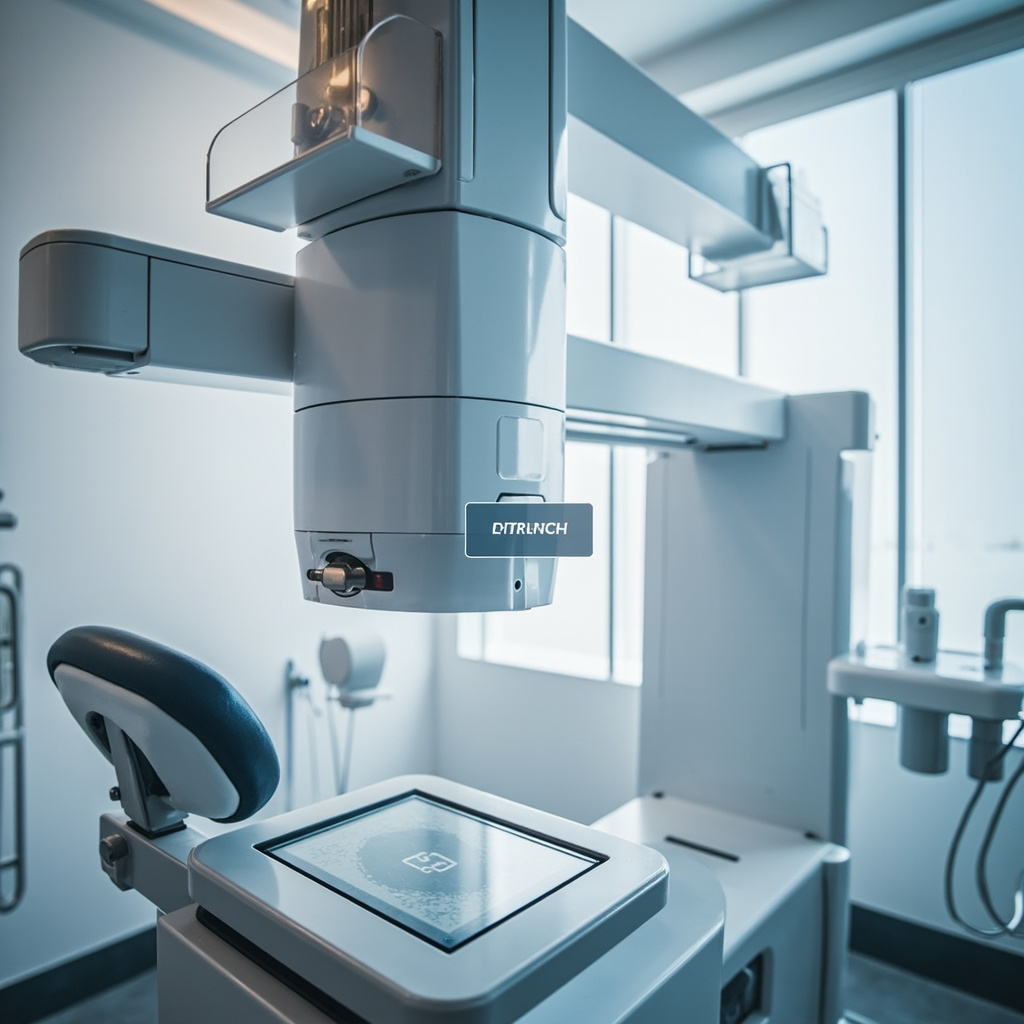
Understanding Collimator Function and Common Misalignment Issues
The collimator assembly controls X-ray beam size and shape, working in conjunction with the PID to ensure proper alignment with the receptor. When these components aren’t properly aligned, several characteristic artifacts appear in radiographic images.
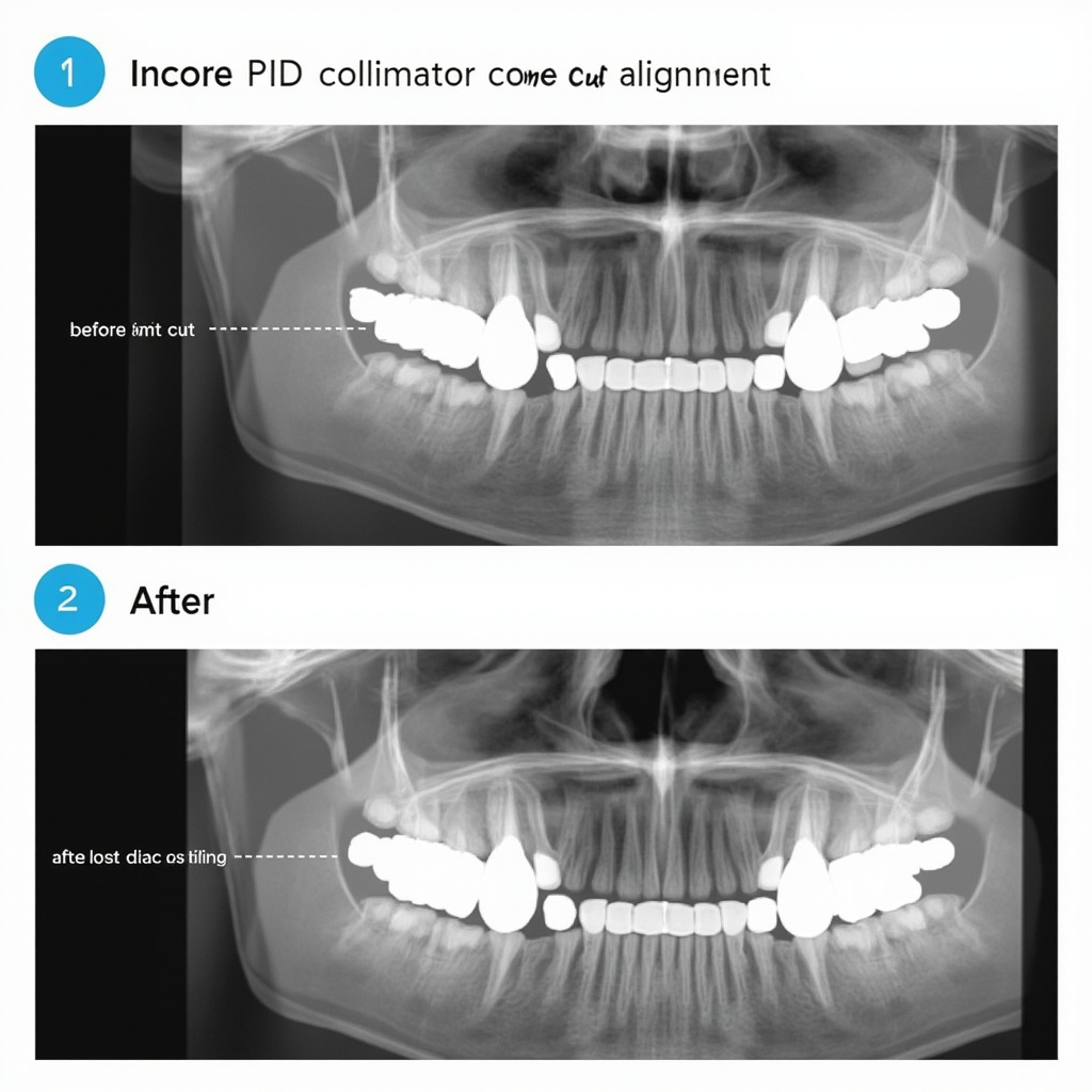
Common alignment issues include angular misalignment between the PID and collimator housing, mechanical wear in positioning joints, and calibration drift in automated positioning systems. These problems manifest as cone cuts where portions of the receptor remain unexposed, creating characteristic crescent-shaped clear areas on the image.
Diagnostic Procedures for Collimator Alignment
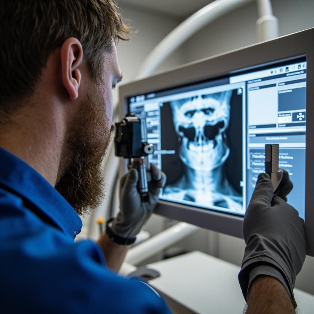
Service technicians should begin troubleshooting with a systematic visual inspection of the collimator assembly. Check for loose mounting hardware, worn pivot joints, and damaged alignment indicators. The PID must maintain flush contact with the collimator housing throughout the full range of motion.
Use alignment test tools to verify beam centering accuracy. Position a test receptor and alignment device, ensuring the PID is flush against the alignment ring. Any gaps or angular discrepancies indicate mechanical adjustment requirements.
Testing Beam Coverage and Centering
Perform test exposures using standardized positioning aids to verify beam coverage matches receptor dimensions. Proper alignment should provide complete receptor coverage with minimal beam overlap beyond the receptor edges. Document any coverage deficiencies with measurements and photographic evidence.
Mechanical Adjustment and Calibration Procedures
Most collimator alignment corrections require mechanical adjustment of mounting hardware and positioning mechanisms. Begin with the primary mounting assembly, checking torque specifications on all fasteners and adjusting as necessary.
For systems with automated positioning, recalibrate the positioning sensors and verify proper communication between the control system and positioning motors. Document all adjustment values and test results according to manufacturer specifications.
PID Alignment Verification
After mechanical adjustments, verify PID alignment using precision measurement tools. The PID cone must maintain parallel alignment with the receptor plane throughout the adjustment range. Angular deviations exceeding 2 degrees typically require additional mechanical correction.
Test the full range of motion, ensuring smooth operation without binding or excessive play in positioning joints. Replace worn components as identified during testing procedures.
Quality Assurance and Final Testing
Complete alignment verification requires comprehensive testing using standardized phantoms and exposure protocols. Perform multiple exposures at different positioning angles, documenting beam coverage consistency and image quality parameters.
Verify that automatic exposure control systems properly compensate for positioning variations. Record exposure timing accuracy and consistency across the full range of positioning options.
Documentation and Service Records
Maintain detailed service records documenting all alignment measurements, adjustment procedures, and final verification results. Include before and after test images showing alignment improvements and compliance with manufacturer specifications.
Provide the customer with calibration certificates and recommended maintenance schedules to prevent future alignment issues. Schedule follow-up inspections according to regulatory requirements and manufacturer recommendations.