Electrical Voltage Fluctuations in Dental X-Ray Equipment: Comprehensive Troubleshooting and Repair Guide
Voltage fluctuations represent one of the most challenging electrical issues affecting dental X-ray equipment performance. These power variations can cause inconsistent image quality, equipment malfunctions, and potentially expensive component failures. Understanding how to diagnose and resolve voltage-related problems is essential for maintaining reliable radiographic operations.
Understanding Voltage Requirements in Dental X-Ray Systems
Modern dental X-ray equipment typically requires stable single-phase or three-phase power supplies ranging from 208-240 VAC. Line voltage below 208V often necessitates step-up transformers, while voltages exceeding specification can damage sensitive electronic components. The high-voltage generator converts these input voltages to the kilovoltage levels required for X-ray production, making stable input power crucial for consistent performance.
Dental X-ray systems are particularly sensitive to power fluctuations because they rely on precise voltage control for exposure parameter accuracy. When input voltage varies, the resulting kVp and mAs settings can deviate from intended values, directly affecting image quality and patient radiation dose.
Common Voltage Fluctuation Symptoms and Indicators

Voltage-related issues manifest in various ways that skilled technicians can identify through systematic observation:
- Inconsistent Image Density: Images appear too light or dark despite consistent exposure settings
- Exposure Timer Inaccuracy: Actual exposure times deviate from programmed values
- Generator Error Messages: Control panels display voltage warnings or fault codes
- Equipment Resets: Spontaneous system shutdowns or parameter resets during operation
- Tube Heating Issues: Excessive tube temperature warnings or premature tube failure
- Control Panel Flickering: Display instability or intermittent control responses
These symptoms often correlate with facility electrical issues such as inadequate service capacity, loose connections, or aging transformers. Environmental factors including HVAC load cycling and equipment startup surges can also contribute to voltage instability.
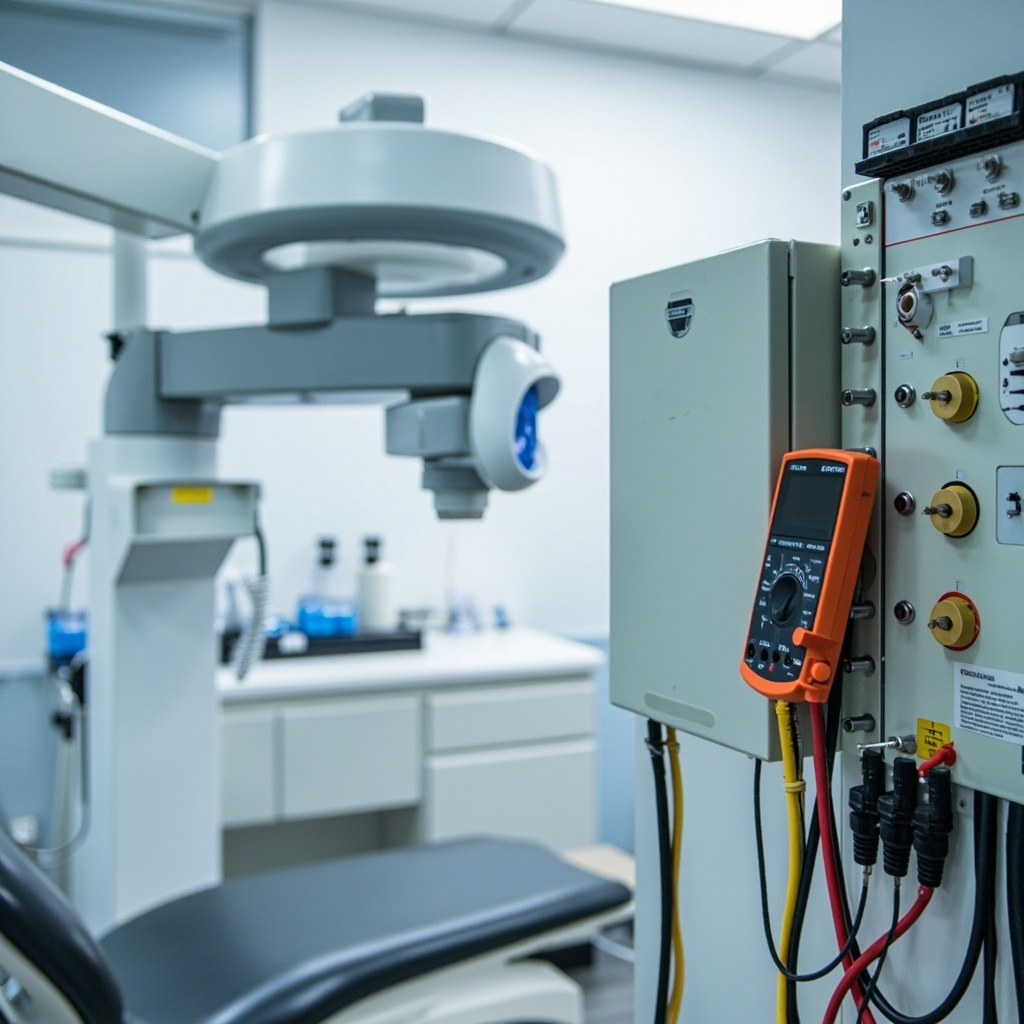
Diagnostic Testing Procedures for Voltage Issues
Effective voltage troubleshooting requires systematic measurement and documentation of electrical parameters. Begin diagnostics with proper safety protocols, ensuring all personnel understand electrical hazards and appropriate protective measures.
Initial Voltage Measurements:
- Use calibrated digital multimeters with true RMS capability
- Measure line voltage at the equipment input terminals
- Record voltage readings during idle, standby, and exposure conditions
- Document voltage variations over extended monitoring periods
Load Testing Protocol:
- Monitor voltage stability during maximum exposure settings
- Test with various tube positions and angulation settings
- Evaluate voltage drop during concurrent equipment operation
- Assess power supply recovery time following exposure cycles
Advanced diagnostics may require oscilloscope analysis to identify voltage waveform distortion, harmonic content, or transient spikes that can affect equipment operation. Power quality analyzers provide comprehensive data on voltage stability, frequency variations, and power factor measurements.
Generator and Power Supply Component Troubleshooting
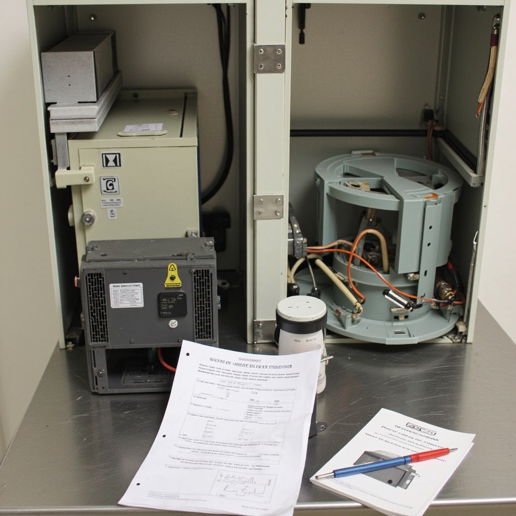
Internal power supply components require methodical testing to isolate voltage-related failures. High-voltage generators contain multiple transformer stages, rectifier circuits, and regulation systems that can contribute to voltage instability.
Transformer Testing:
- Verify primary winding continuity and insulation resistance
- Test turns ratio accuracy across all voltage taps
- Check for overheating, discoloration, or oil leakage
- Measure no-load and full-load voltage regulation
Rectifier Circuit Analysis:
- Test high-voltage rectifier diodes for forward and reverse characteristics
- Evaluate filter capacitor condition and ripple voltage levels
- Verify voltage regulation circuit operation and feedback systems
- Check for component aging or thermal stress indicators
Many modern systems incorporate voltage compensation circuits that automatically adjust for input variations. These systems require calibration verification and may need reprogramming following component replacement or facility electrical modifications.
Facility Electrical System Evaluation
Comprehensive voltage troubleshooting extends beyond the X-ray equipment to include facility electrical infrastructure assessment. Poor building electrical systems often contribute to equipment voltage problems.
Service Panel Inspection:
- Verify adequate service capacity for total facility electrical load
- Inspect panel connections for looseness, corrosion, or overheating
- Check circuit breaker condition and proper sizing
- Evaluate grounding system integrity and resistance measurements
Wiring and Distribution Assessment:
- Test conductor resistance and voltage drop calculations
- Verify proper circuit sizing for equipment amperage requirements
- Check for aluminum wiring or obsolete installation methods
- Evaluate dedicated circuit requirements and isolation needs
Aging facilities may require electrical system upgrades to support modern digital X-ray equipment. Consultation with qualified electrical contractors ensures compliance with current codes and optimal equipment performance.
Repair Solutions and Voltage Stabilization Methods
Effective voltage problem resolution often requires multiple approaches depending on root cause identification. Solutions range from simple adjustments to comprehensive system upgrades.
Equipment-Level Solutions:
- Voltage regulator installation for input power conditioning
- UPS systems with voltage regulation and surge protection
- Transformer tap adjustment for voltage optimization
- Component replacement for failed regulation circuits
Facility-Level Improvements:
- Dedicated circuit installation for X-ray equipment isolation
- Service panel upgrades for increased capacity and reliability
- Power factor correction to improve electrical efficiency
- Surge suppression systems for transient protection
Preventive maintenance programs should include regular voltage monitoring, connection tightening, and electrical system inspection. Documentation of voltage trends helps identify developing problems before equipment failure occurs.
Prevention and Monitoring Strategies
Long-term voltage stability requires ongoing monitoring and proactive maintenance approaches. Establishing baseline measurements allows early detection of deteriorating conditions.
Install permanent voltage monitoring systems where chronic problems exist. These systems provide continuous data logging and alarm capabilities for immediate problem notification. Regular calibration ensures measurement accuracy and reliability.
Staff training on voltage-related symptoms empowers operators to recognize developing problems and request service before complete failures occur. Comprehensive documentation of electrical issues supports warranty claims and helps identify recurring problems requiring systematic resolution.
Coordination with facility maintenance teams ensures electrical system changes consider X-ray equipment requirements. Planned electrical work should include voltage impact assessment and equipment protection measures.