The Intermittent Sensor: Diagnosing Cable, Connector, and USB Faults That Kill Digital Intraoral Images

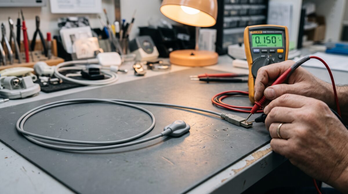
The call comes in the same way almost every time. The sensor works fine for the first three patients, then the software throws a “device not detected” error, then it works again after someone jiggles the cable. By the time you arrive it is behaving perfectly, and the front desk is convinced the whole unit needs replacing. It almost never does. A digital intraoral sensor is a rugged silicon chip inside a sealed housing, and that chip rarely fails. The cable that feeds it, bent and yanked and autoclaved-adjacent thousands of times a year, is a different story. This is how you find the break before anyone writes a five-figure purchase order.
Why the Cable Fails Before the Chip Does
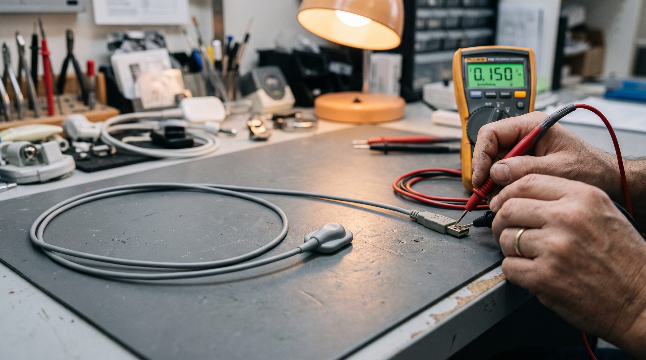
A modern CMOS or CsI intraoral sensor is engineered to survive being bitten, dropped, and wiped down between every patient. The imaging area is the tough part. The vulnerable part is the flat, flexible cable that carries power and high-speed data out of the sensor head, through a strain-relief boot, along a metre or more of jacket, and into a USB or proprietary connector.
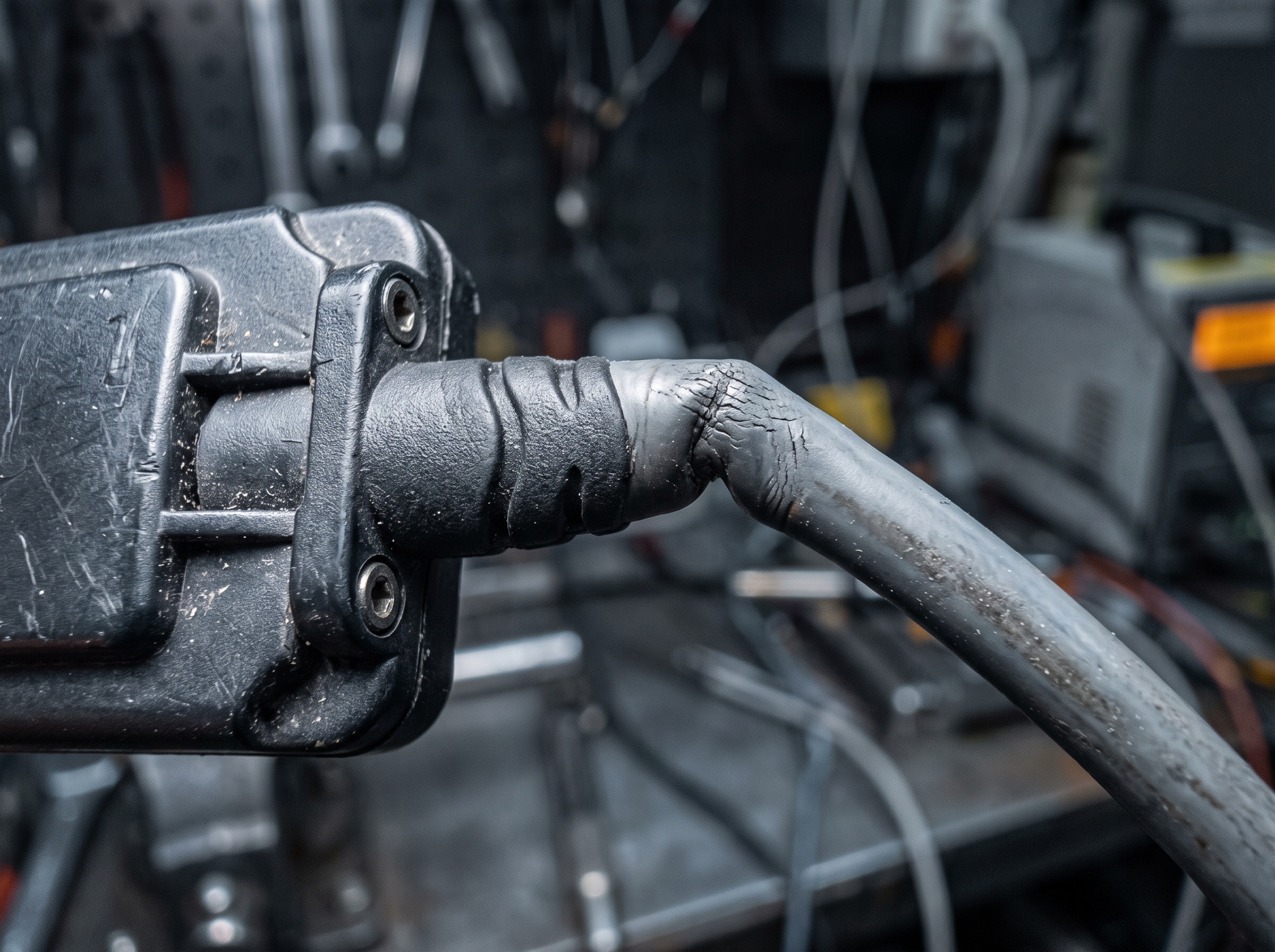
Every one of those transitions is a stress concentrator. The strain-relief boot at the sensor head sees the sharpest and most repetitive bending, because operators route the cable around the patient’s cheek and anchor it with a finger. Inside that jacket are dozens of hair-thin conductors. Flex them tens of thousands of times and they work-harden and fracture, often while the insulation around them looks perfectly intact. That is the entire reason these faults present as intermittent: the broken ends still touch when the cable sits one way and separate when it moves.
Reading the Symptom: What “Intermittent” Actually Tells You
Before you touch a tool, interview the failure. The pattern of an intermittent fault is diagnostic on its own.
A sensor that drops out only in specific mouth positions, or only for certain operators who route the cable tightly, points hard at a flex break near the head. A sensor that fails when the cable is bumped at the desk, or when the connector is nudged, points to the connector shell or the solder joints behind it. A sensor that images fine but throws communication or timeout errors under load can be a data-line break rather than a power-line break. And a fault that appears only after the operatory PC has been running a while, affecting more than one device on the same hub, is often not the sensor at all — it is the USB bus. Separating those buckets first saves you from chasing a cable that was never the problem.
First, Rule Out Everything That Isn’t the Sensor
Discipline here prevents expensive mistakes. Work from the PC outward before you condemn the sensor.
Move the sensor to a known-good USB port directly on the PC, never through an unpowered hub or a front-panel extension, and preferably a USB port you have confirmed with another device. Confirm the sensor’s driver and capture software see the device in their own hardware list, and check the operating system’s device manager for a device that appears and disappears as you handle the cable. Swap the docking bridge, holder, or remote module if the system uses one; those interface boxes and their own captive cables fail just as readily as the sensor cable. Reboot once to clear a hung driver. Only when the port, the hub, the bridge, the driver, and the software are all cleared do you have a genuine sensor-side fault worth opening a bench ticket for.
Isolating the Break: A Bench Procedure
With the sensor isolated as the suspect, the goal is to localise the break to the connector, the strain relief, or a mid-cable crush point. The fastest confirmation is a swap test: install a known-good sensor of the same model on the same port and software. If the replacement is rock-solid, the fault is in the original sensor assembly, full stop.
Next comes the controlled wiggle test. With the imaging software’s live device status or a continuous-detection view on screen, gently flex the cable in small sections, starting at the connector and walking toward the head. Watch for the exact position that drops or restores the connection. A fault that reproduces reliably within two centimetres of the strain-relief boot is a textbook flex break; a fault that only appears when you rock the connector shell is a connector or solder failure.
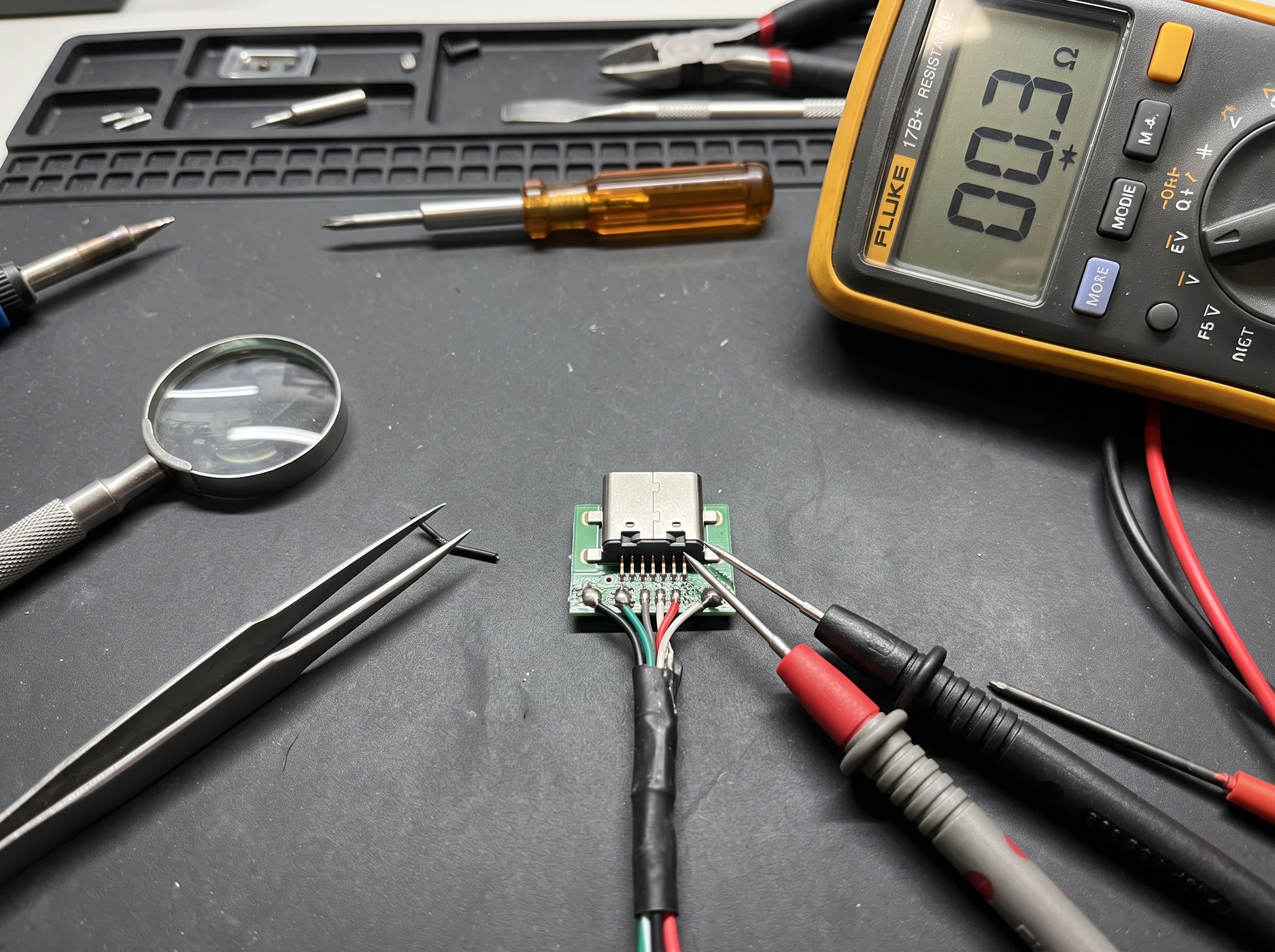
For a defensible diagnosis, back the wiggle test with continuity measurement. With the sensor safely disconnected, meter the individual conductors end to end where the connector pinout is accessible, and flex the suspect zone while watching for the reading to open. An intermittent open under flex is your proof. Never probe a live bus, and never open a sealed sensor housing you do not intend to send out for professional repair — breaching the seal ends any refurbishment option and can void coverage.
Repair or Replace? Making the Call
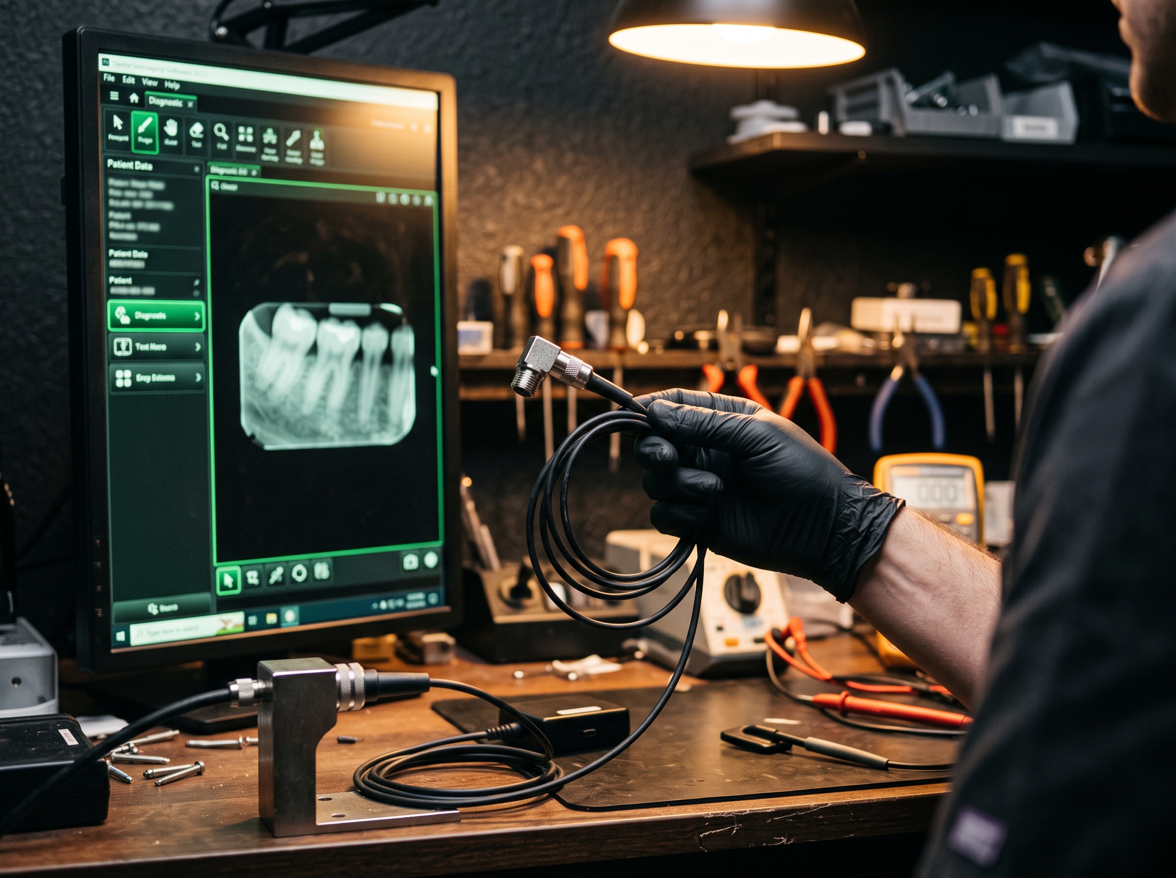
Here is the good news for the practice owner: a cable or connector fault is one of the most repairable problems in dental imaging. Specialist sensor-repair houses routinely replace cables, reterminate connectors, and rebuild strain reliefs on Schick, Dexis, Carestream, Gendex, and similar sensors for a fraction of a new unit’s price, and many turn the job around in days rather than weeks. When the imaging chip is intact and only the cable has fractured, repair or refurbishment is almost always the economically correct answer.
Replacement earns its keep in a narrower set of cases: visible damage to the sensor housing or active area, water or chemical intrusion past the seal, a model old enough that repair parts are scarce, or a practice that simply cannot tolerate any downtime and keeps a spare in rotation. The disciplined move is to keep one validated spare sensor per operatory group so a cable failure becomes a same-day swap and the broken unit ships out for repair instead of triggering a panic purchase.
Preventing the Next Cable Death
Every cable fault you fix is a chance to change the handling that caused it. The failures are mechanical, so the prevention is mechanical too.
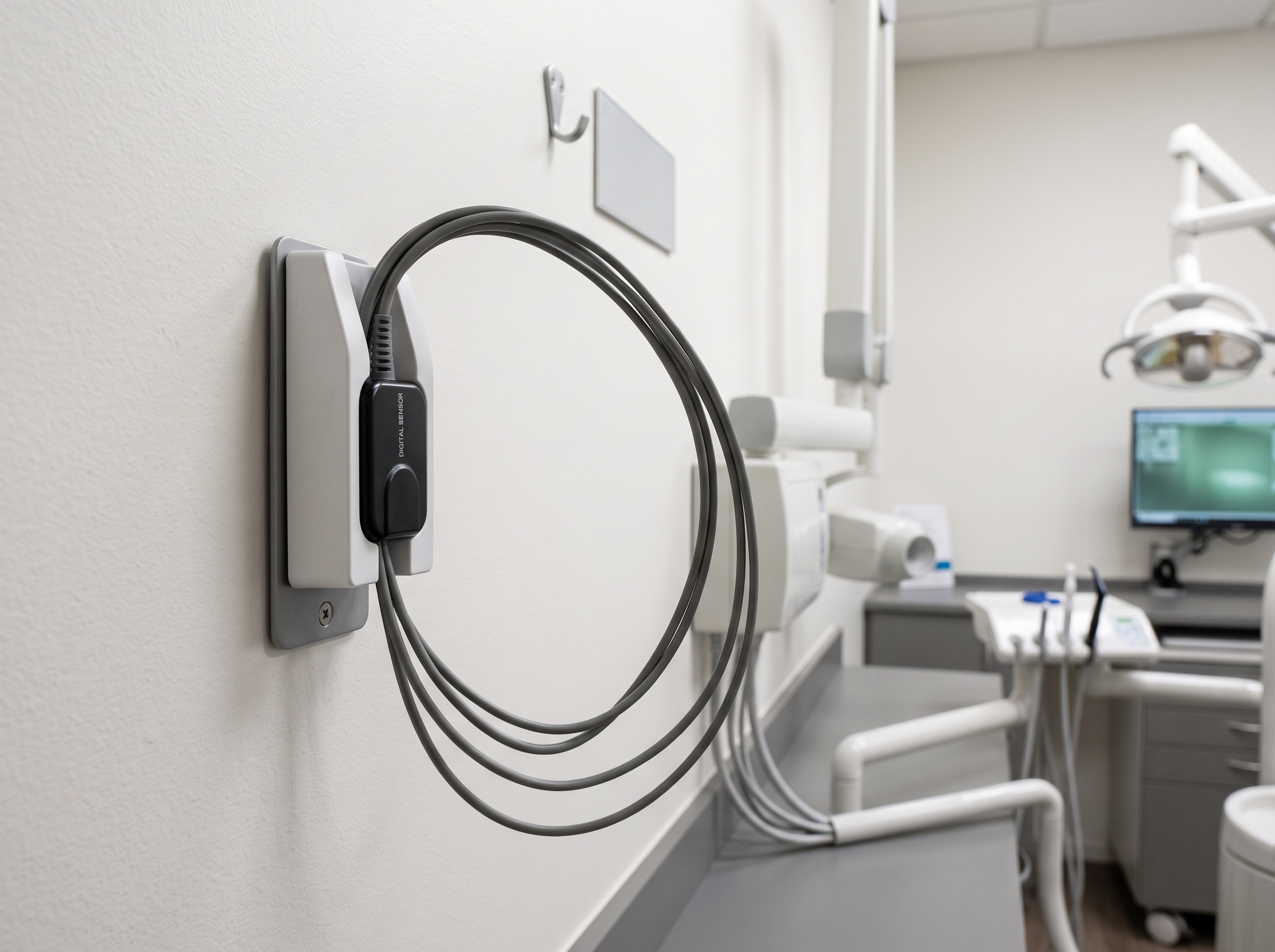
Train operators to route the cable in wide, gentle curves and to anchor it at the connector body rather than pulling on the cable itself. Ban the habit of wrapping the cable tightly around a hand or a bracket between patients. Store each sensor in a wall cradle or a dedicated holder with the cable coiled in a loose loop, never crammed into a drawer where the door crushes it or looped through a chair arm where it kinks at the same spot daily. Inspect the strain-relief boot during routine maintenance visits and flag any stiffening, cracking, or discolouration before it becomes a fracture. Where the manufacturer offers a protective cable sheath or a reinforced boot, fit it; it is far cheaper than a repair. And keep a short log of which sensor and which operatory the intermittent calls come from, because a cluster of faults usually traces back to one handling habit you can correct at the source.
An intermittent sensor is one of the most reassuring faults in the service catalogue once you know its anatomy: it looks catastrophic to the practice and is usually a cable the length of your forearm. Work the diagnosis from the PC outward, isolate the break with a swap and a wiggle test, confirm it with continuity, and let a repair specialist rebuild what handling wore out. Reserve outright replacement for genuine chip or housing damage. Do that, and you turn a five-figure scare into a bench ticket — and if the housing seal is compromised or the fault refuses to localise, that is the point to route the sensor to professional repair rather than pressing on.
Sources & further reading: