Concentric Rings on a CBCT Scan: Diagnosing Flat-Panel Detector Gain and Defective-Pixel Faults


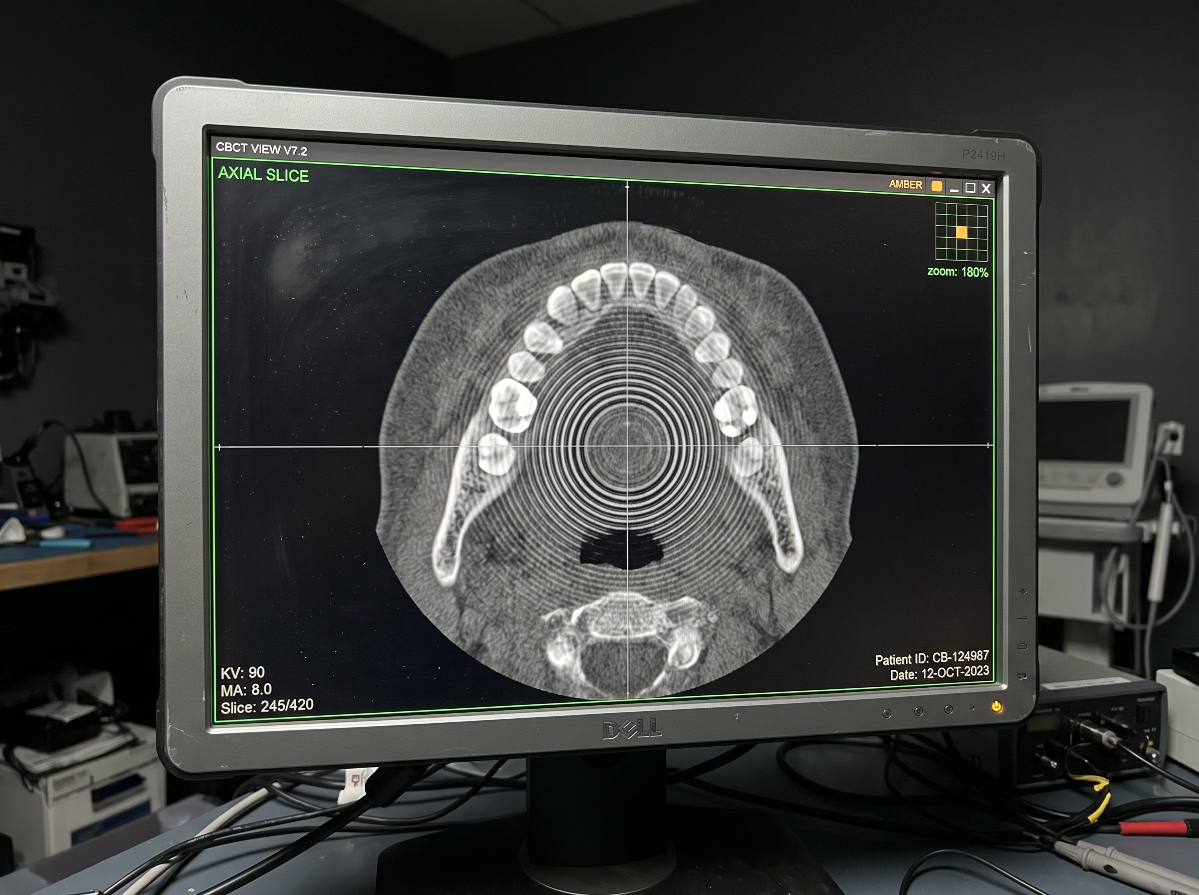
A clinician forwards a CBCT volume with a complaint that sounds almost cosmetic: “there are circles in the scan.” On the axial slices you see them immediately — thin, perfectly round rings, all sharing the same center, sitting on top of the anatomy like ripples on a pond. It is tempting to dismiss them as a reconstruction quirk or to reach straight for a new detector. Both reactions are usually wrong. A ring artifact is one of the most diagnosable faults in cone-beam imaging precisely because its geometry gives it away: it is almost always a stationary detector defect, projected into a circle by the physics of the scan. This is the service procedure for confirming that, isolating which part of the detector chain is responsible, and correcting it — often without replacing a single component.

Why a Detector Defect Becomes a Perfect Circle
To troubleshoot rings efficiently you have to understand where they come from, because the mechanism points straight at the cause. During a CBCT acquisition the source and flat-panel detector rotate around the patient while the panel captures hundreds of projection frames. Reconstruction then back-projects those frames into a volume. If a single detector pixel — or a small cluster — reports a consistently wrong value across every frame, that error does not move with the anatomy. It stays locked at the same position on the panel for the whole rotation. When the reconstruction sweeps that fixed error through 360 degrees, it smears it into a ring centered on the axis of rotation.
That geometry is your first and best diagnostic clue. The radius of the ring corresponds to how far the faulty pixel sits from the projection of the rotation axis; a defect near the axis makes a small tight ring, one near the panel edge makes a large one. The key takeaway for the tech is simple: a defect that is fixed on the detector produces a ring, while a defect that moves with the patient does not. That single distinction separates a detector problem, which you can calibrate or repair, from an object or technique problem, which you cannot fix at the panel.
Step One: Confirm It Is the Detector, Not the Object
Before you touch a calibration routine, rule out the artifacts that only imitate detector rings. The most common impostor is the streaking and dark-banding produced by high-density objects — metal restorations, implants, and posts — through beam hardening and photon starvation. Those artifacts radiate from the metal, change with the patient’s anatomy, and are not concentric on the rotation axis. If the “rings” are actually dark streaks fanning out from a crown, you are looking at a physics-of-the-object problem to be managed with positioning, field-of-view selection, and metal-artifact-reduction settings, not a hardware fault.
The definitive test is a phantom or an air scan. Acquire a volume of a uniform cylindrical phantom, or simply an empty field, at a standard technique. A uniform object contains no anatomy to blame, so any concentric ring that survives is unambiguously coming from the imaging chain itself — almost always the detector. If the rings appear in the phantom scan exactly as they did in the patient, you have confirmed a detector or calibration fault and can proceed with confidence. If they vanish, the original artifact was object- or technique-driven and the detector is innocent.
Step Two: Re-run and Read the Gain and Dark-Field Calibration
With the detector confirmed as the source, the cheapest fix comes first, because the majority of ring artifacts are not hardware failures at all — they are stale calibration. A flat-panel detector relies on two reference calibrations to turn raw pixel signal into a usable image. The dark-field (or offset) calibration captures each pixel’s baseline output with no X-rays present, correcting for dark current and electronic offset. The flat-field (or gain) calibration captures each pixel’s response to a uniform exposure, correcting for the fact that no two pixels convert photons identically. Reconstruction assumes both maps are current.
Detectors drift. Dark current changes with temperature and age, and pixel gain shifts over time and with exposure level, so a gain map recorded months ago may no longer describe the panel accurately. When individual pixels have drifted away from their stored calibration, they report values the flat-field correction no longer cancels — and those residual per-pixel errors are exactly what smears into rings. The first action, therefore, is to run the manufacturer’s detector calibration routine: a fresh dark-field capture followed by a fresh flat-field capture at the correct technique, following the service software’s prompts for warm-up and exposure levels. Then re-scan the phantom. In a large share of cases the rings simply disappear, because you have re-taught the correction where every pixel truly sits today. If the ring is fainter but still present, note it — that partial improvement tells you a calibration alone cannot rescue those pixels, which points to the next step.
Step Three: Rebuild the Defective-Pixel Map
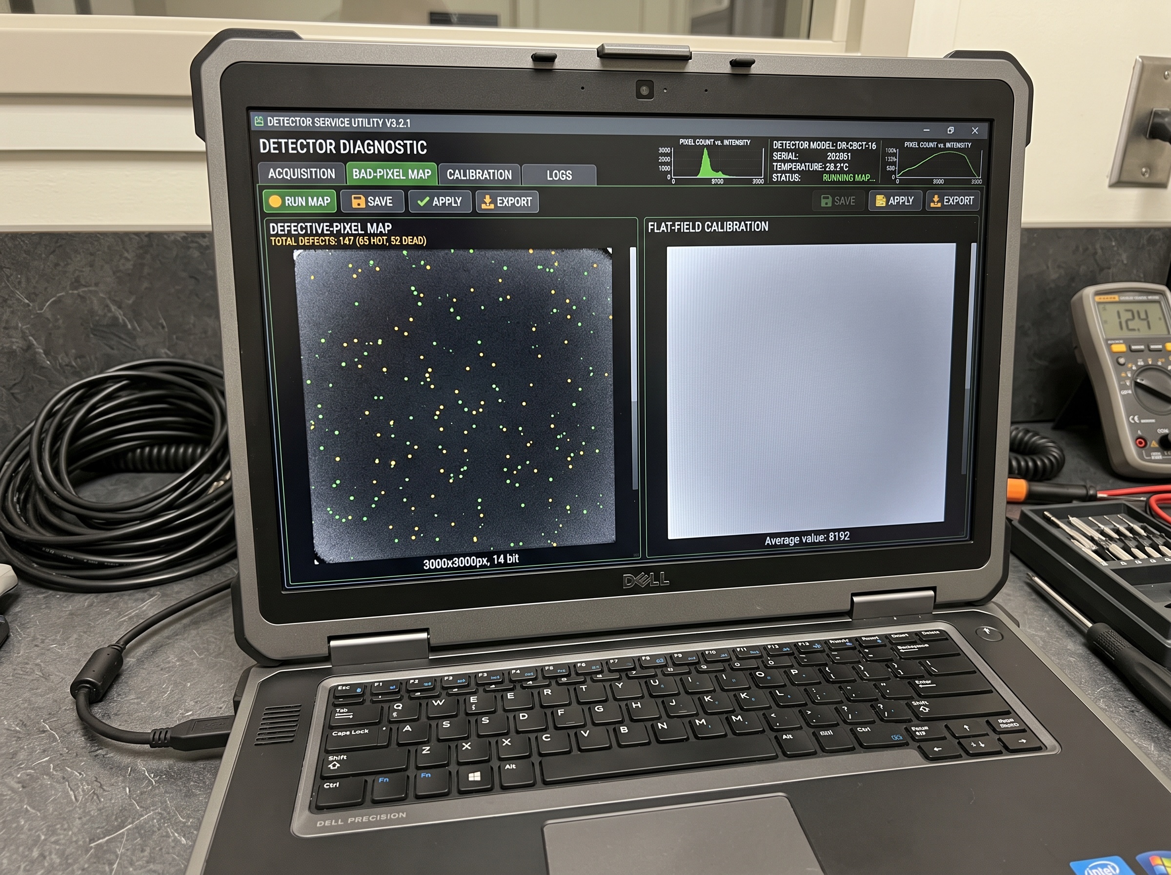
Some pixels are past calibrating. A pixel that is fully dead, stuck, or so noisy that its response is non-linear cannot be corrected by a gain factor, because there is no stable value to scale. For these, the detector maintains a defective-pixel map: a list of bad pixel locations that the correction algorithm interpolates over using their healthy neighbors, so they never reach the reconstruction as errors. Over a panel’s life, new pixels fail, and if the bad-pixel map is not updated, those newly-failed pixels sail straight through into the image as rings.
The service utility for most CBCT detectors can re-run bad-pixel detection: it exposes the panel to controlled dark and flat fields, measures every pixel against tolerance thresholds, and flags outliers — dead, hot, or excessively noisy — adding them to the correction map. Run that detection, let it rebuild the map, and re-scan the phantom. Watch how the count trends over time, too. A map that grows by a handful of pixels a year is a normal aging panel; a sudden jump, a tight cluster of new defects, or a whole bad line or column is a different story and suggests physical or electronic damage rather than gradual wear. If rebuilding the map clears the rings, you are done at the software level. If a ring persists at a location the map now covers, or the defects are clustering, the problem has moved from calibration into hardware.
Cause and Repair: Matching the Fix to the Finding
By this point the diagnosis has sorted itself into layers, and the repair follows the layer you confirmed. Resist the reflex to replace the panel first; it is the most expensive component in the chain and the least often actually at fault.
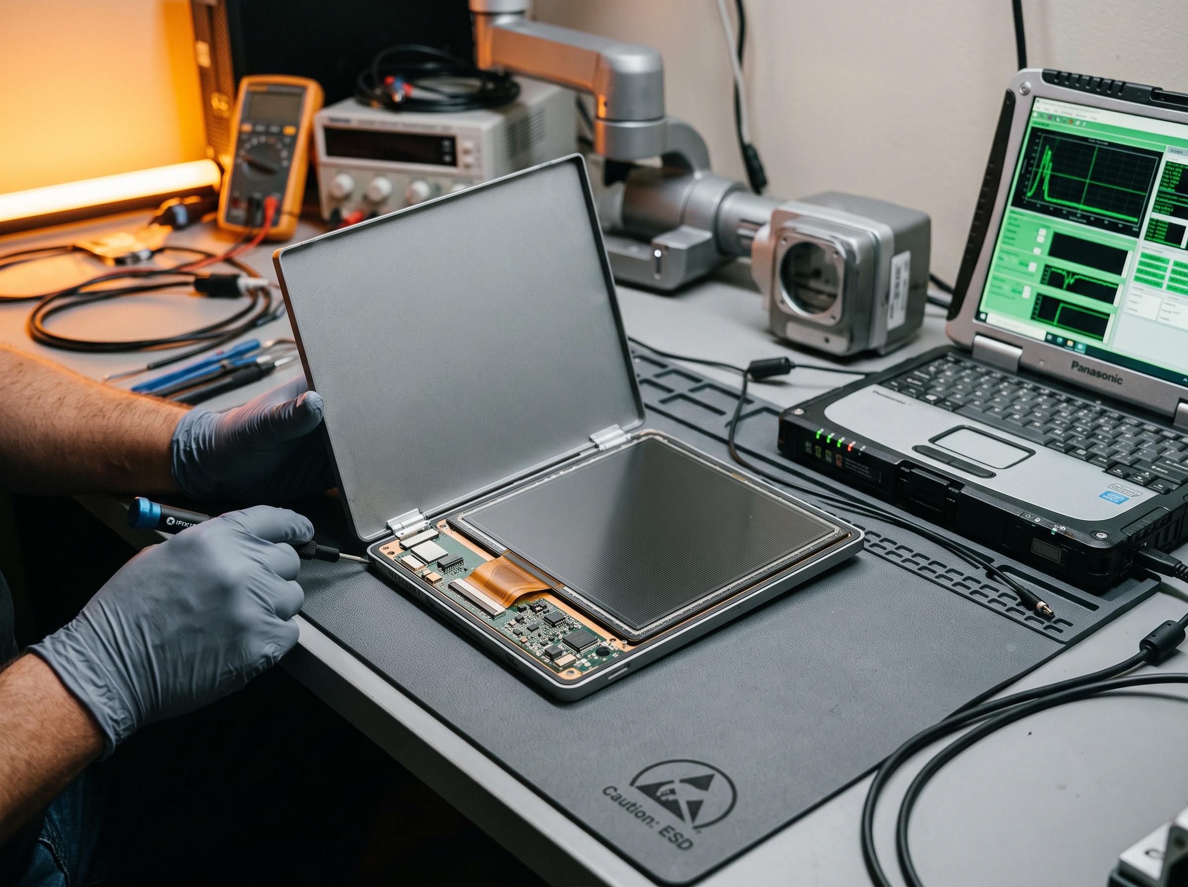
If a fresh gain and dark-field calibration cleared the rings, the fix was simply current calibration, and the real job is prevention — schedule it so it does not lapse again. If rebuilding the defective-pixel map cleared them, a normal number of pixels had aged out of tolerance and the correction is now doing its job. Where rings survive both, look for physical and environmental causes. Detector temperature is a frequent culprit: a panel running hot from poor ventilation, a failing cooling element, or a warm room shifts dark current unevenly and reintroduces rings that calibration cannot hold, so verify airflow and let the unit reach its normal operating temperature before judging. Check the connections next — a marginal detector data cable or a loose ribbon connector can corrupt specific readout lines and produce ring or line artifacts, and reseating or replacing the cable is far cheaper than a panel. A defect map that is exploding, a full dead row or column, or persistent structured non-uniformity after every correction points to genuine panel degradation — a failing readout channel or scintillator damage — and that is the repair-or-replace decision, made with the manufacturer using the panel’s defect trend as evidence. Only when calibration, mapping, thermal, and cabling causes are all excluded is a detector swap the honest answer.
Prevention: A Calibration and Monitoring Cadence
Ring artifacts almost never arrive overnight. Pixels drift and fail gradually, calibrations quietly go stale, and the first person to notice is usually a clinician looking at a patient scan — the worst possible moment. A light preventive routine moves that discovery back into your control. Start with a documented baseline: when a unit is verified good, run and archive a uniformity-phantom scan along with the current pixel-defect count, and keep both in the equipment file so “normal” for this panel is written down rather than remembered.
From there, run the manufacturer’s detector calibration on the interval they specify, and do not let it lapse — a lapsed gain map is the single most common preventable cause of rings. On a fixed cadence, re-scan the uniformity phantom and compare against the stored baseline, watching for faint rings, rising noise, or a climbing defect count as an early warning that the panel is drifting. Track the defective-pixel total as a trend line, because a slow rise is expected aging while a sharp step is a fault to investigate now. Keep the detector within its rated temperature range by maintaining ventilation and giving the unit its warm-up time, since thermal stability does as much for ring-free images as any calibration. Log every ring complaint with the unit, technique, and what cleared it, so patterns surface across your fleet. Do all of that and the payoff is concrete: the next time a clinician reports circles in a scan, you already know that panel’s baseline, and isolating the cause is a phantom scan and a calibration run — minutes of work — not a guessed-at parts order.

Concentric rings look alarming and diagnose easily once you read them as geometry: a fixed error on the detector, spun into a circle by the scan. Confirm the detector with a phantom, refresh the gain and dark-field calibration, rebuild the defective-pixel map, and only then weigh temperature, cabling, and panel health. Work the chain in that order and keep documented baselines so you always know what a clean panel looks like, and you will stop condemning good detectors — and stop letting a stale calibration masquerade as a hardware failure.
Sources & further reading: