The Unit Fires but Nothing Happens: A Diagnostic Tree for No-Exposure Faults


Few faults empty a dental operatory’s schedule faster than an X-ray unit that simply will not fire. The patient is positioned, the sensor is placed, the assistant steps out and presses the switch, and nothing happens. No beep, no exposure indicator, no image. It is a fault with a hundred possible causes, which is exactly why guessing is the worst way to approach it. Swap a handswitch, then a fuse, then a board, and you can burn an afternoon and a parts budget without ever finding the problem. The reliable method is a diagnostic tree: define the fault precisely, then walk the firing chain from the wall socket to the tube in order, proving each stage before you move to the next. This guide lays that tree out stage by stage.
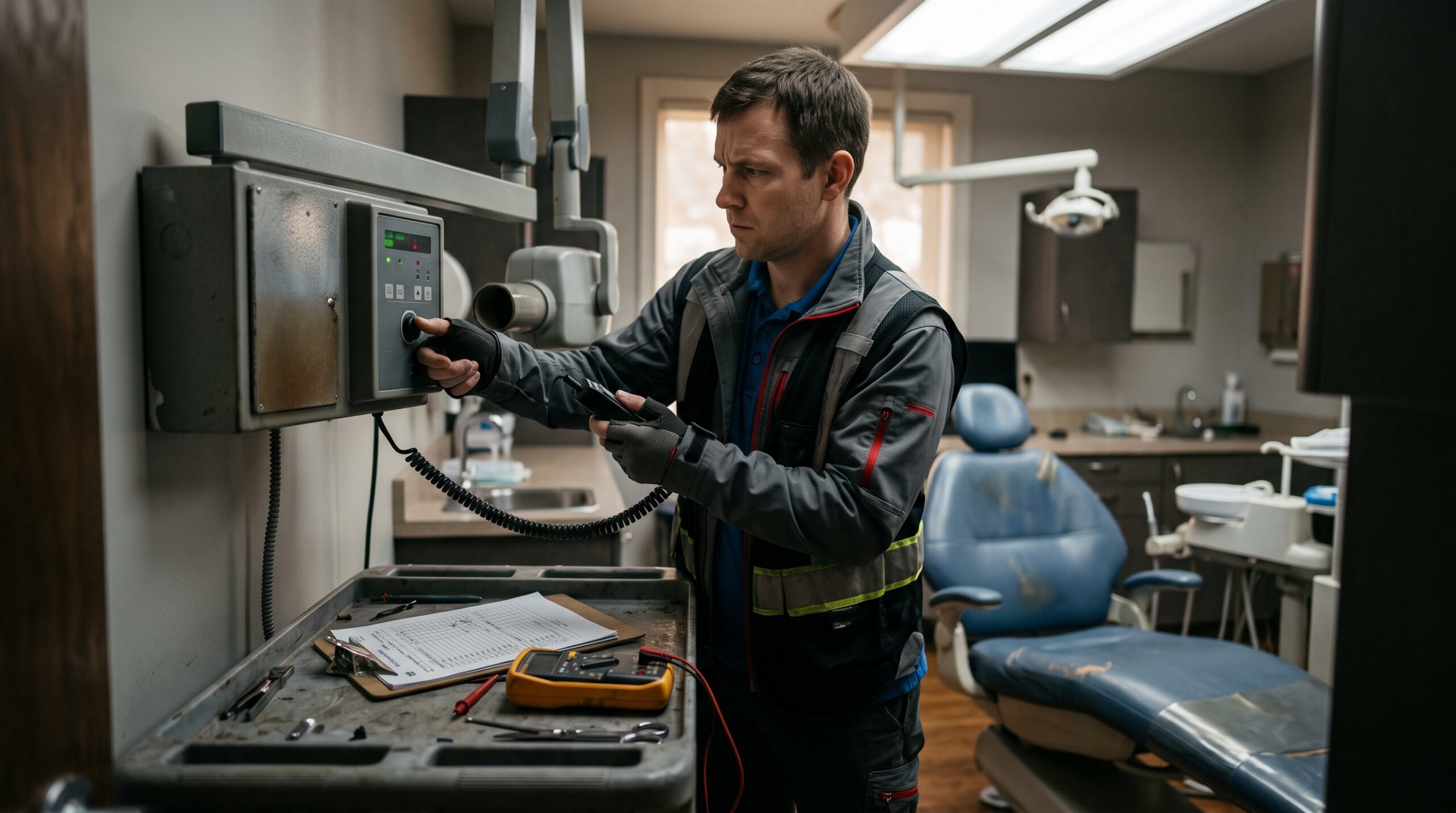
First, define the fault and respect the hazard
“Nothing happens” is not one symptom, and the distinction narrows the search immediately. A unit that is completely dark — no panel lights, no ready indicator, no fan — is almost certainly a power or upstream-control problem. A unit that powers up, shows a ready state, and beeps or cycles when you press expose but produces no image is a different animal: power is fine, and the fault sits in the exposure sequence, the high-voltage stage, or the tube itself. And a unit that appears to fire normally but yields a blank or black image may not be a generator fault at all, but a detector, acquisition, or software problem masquerading as one. Establish which of these you have before touching a tool.
Then respect what you are working on. A dental X-ray generator steps mains voltage up to tens of thousands of volts, and its high-voltage section and any smoothing capacitors can hold a dangerous charge after the unit is switched off and unplugged. Never open a tubehead or a high-voltage compartment. Confine field diagnosis to what you can safely reach: the mains supply, the exposure switch and its cabling, external interlocks, accessible fuses, and whatever the control system reports. The moment the tree leads inside the high-voltage housing, the job belongs to a qualified service engineer with the right discharge tools.
Start at the wall: mains power and fuses
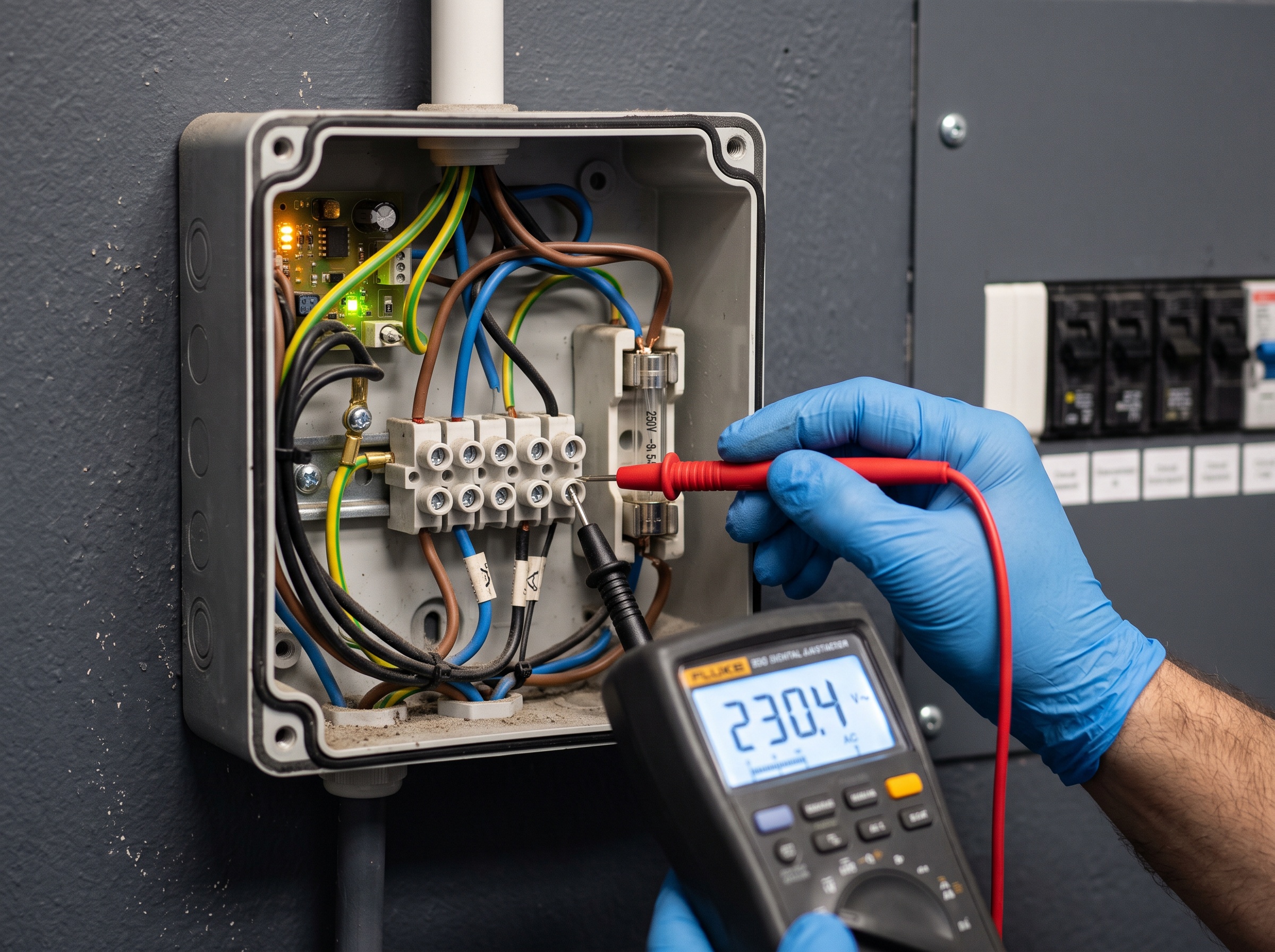
If the unit is completely dead, begin where the electricity does. Confirm the wall outlet is live with a known-good device or a multimeter, because a tripped circuit breaker, a GFCI that has popped, or a dead outlet is the single most common cause of a totally unresponsive unit — and the least expensive to fix. Dental X-ray units are frequently on shared circuits with other operatory equipment, so a breaker that trips when a compressor or sterilizer kicks in is a classic intermittent culprit worth asking the staff about.
With supply confirmed, check the unit’s own power path: the on/off switch, the line cord and plug, and any accessible cartridge fuses in the power junction box or on the incoming board. A blown line fuse gives you a dead unit and a clear next question — why did it blow? A fuse that fails again the instant you replace it is telling you about a short or an overload downstream, not asking to be replaced a second time. Note that and stop; do not keep feeding fuses into a fault. Only when the unit has stable mains power and still shows no life do you move up the chain.
The exposure switch: a two-stage dead-man control
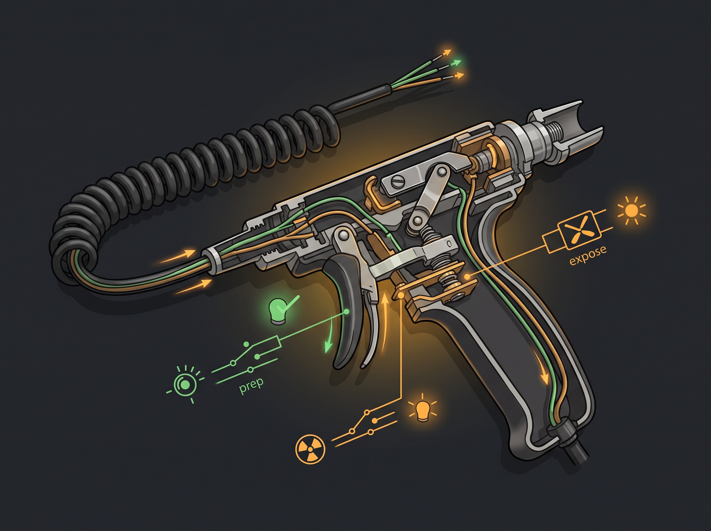
When the unit powers up and reaches a ready state but will not expose, the handswitch is the highest-yield suspect, because it is the most-handled, most-flexed component in the whole system. Critically, a dental exposure switch is a two-stage dead-man control. The first press (prep) commands the tube to boost its filament and rotate up to readiness; the second press (expose) actually triggers the shot. Both stages must make and hold their contact for the full exposure, and a fault in either one stops everything.
Two failure patterns dominate. First, a broken conductor inside the coiled cable, usually near the strain reliefs at each end where years of flexing fatigue the wire. Second, worn or dirty contacts inside the switch itself. The symptoms are telling: if the unit reaches ready (you hear or see prep succeed) but never fires, the expose stage or its wire is suspect; if nothing happens at all on the first press, prep is not getting through. With the unit safely in a testable state per the manufacturer’s service instructions, a continuity check across each stage of the switch while it is pressed will confirm a dead contact or an open cable run. A handswitch is an inexpensive, common-wear part, but prove it before you replace it — swapping in a known-good switch is a fast confirmation when you have one.
Interlocks and safety circuits: the silent vetoes
Modern X-ray systems are wired so that a number of safety interlocks can quietly veto an exposure, and an open interlock produces the same “press and nothing happens” symptom as a genuine failure. This is a stage technicians skip and then chase for hours. Depending on the installation, an exposure can be inhibited by a door interlock, a tube-selector or room-selector switch left in the wrong position, a warning-light circuit the system monitors, or a fault flag from the detector or acquisition PC that has not cleared.
Work these deliberately. Confirm any door or room interlock is closed and functioning. Verify that any multi-tube or multi-room selector is actually pointing at the tube you are trying to fire — a selector on the wrong operatory is a genuinely common and maddening cause. In integrated digital systems, make sure the acquisition software is armed and waiting for an exposure; many units will refuse to fire until the software says it is ready to receive an image, so a hung or un-launched application reads at the tubehead as a dead unit. Ruling the interlocks out here saves you from condemning good hardware.
The timer and control board: let the system tell you
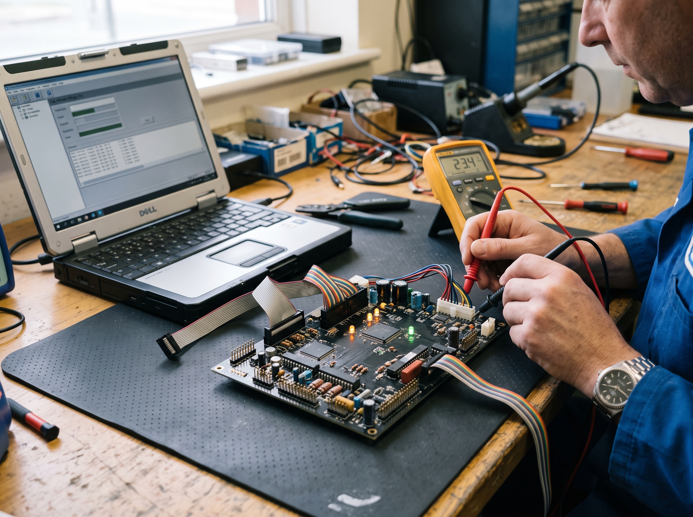
If power is solid, the switch proves good, and no interlock is open, the fault moves into the control electronics — the timer and the main control board that sequence the exposure. The good news is that modern generators rarely fail silently here. Most surface a fault or error code on the panel, and that code is the fastest route to the answer. Record it exactly and cross-reference the manufacturer’s service documentation before doing anything else; a code frequently names the failing subsystem — filament circuit, kV feedback, timer, communication — and turns a broad search into a targeted one.
Communication faults deserve special mention on networked and digital units. When the control board cannot talk to the operator panel, the detector, or the acquisition PC — a failed cable, a loose connector, a comms board fault — the exposure sequence will not complete even though every individual piece is healthy. Reseat the data and control connectors, inspect ribbon and comms cabling for damage, and confirm the panel and board are actually handshaking. Beyond reading codes, reseating connectors, and cycling power, board-level diagnosis and replacement is manufacturer-specific work; follow their procedure or hand it off rather than probing a live board blind.
The high-voltage and tube stage: the end of the field tree
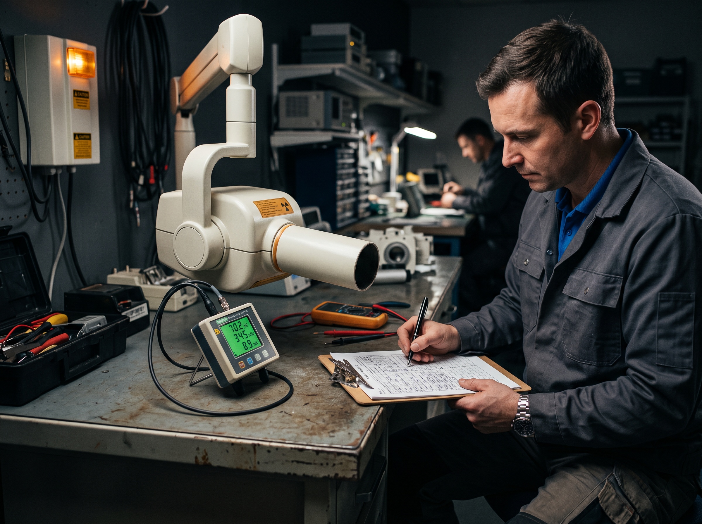
When power, the exposure switch, the interlocks, and the control system all check out, and the unit still produces no radiation, the fault has reached the high-voltage generation and tube stage — and this is where field diagnosis stops. A failed high-voltage transformer or supply, an open or burned-out filament that can no longer boil off electrons, or an end-of-life tube will all present as a unit that goes through the motions but emits nothing. Confirming which requires energized high-voltage measurements and, ultimately, access to the sealed housing, both of which demand a qualified service engineer and proper discharge and safety equipment.
What you can and should do is verify the result and document the trail. A non-invasive kV and dose meter placed in the beam confirms objectively whether any radiation is being produced when the unit is triggered — turning “I think it’s not firing” into a measured fact. Capture that reading, the fault code, and every stage you cleared, and hand a complete picture to the service provider. A tube or high-voltage failure is the expensive end of the tree, but arriving there through elimination — rather than by guessing — means the practice is not paying for a tube when the real fault was a two-dollar fuse or a selector switch.
Prevention: make the next failure faster to solve
A no-exposure fault is rarely preventable outright — switches wear, fuses blow, tubes age — but you can make every future occurrence far quicker to resolve. Keep the unit on a properly rated, ideally dedicated circuit to cut nuisance breaker trips, and treat the handswitch cable gently: no sharp bends, no dangling weight, no rolling a stool over it, since cable fatigue is one of the most frequent causes you will meet. Log every fault code and every repair against each unit, so a recurring code becomes an obvious pattern rather than a fresh mystery each time. Fold a functional exposure check and a look at the switch cable into routine preventive maintenance, and keep a known-good spare handswitch on the shelf for the practices you serve — it is the cheapest way to clear or confirm the single most common cause in minutes.
Above all, resist the urge to jump straight to the expensive part. The discipline of the tree — wall, switch, interlocks, control board, high voltage, in that order — is what separates a ten-minute fix from a wasted afternoon. And when the tree leads you into the high-voltage housing, that is not a failure of your diagnosis; it is precisely the point at which a documented, methodical handoff to professional service protects both you and the patient.