Dead Pixels, Ghosting, and Banding: Diagnosing Image-Quality Faults in a Digital Intraoral Sensor


A digital intraoral sensor that has stopped connecting is a straightforward call: you chase the cable, the connector, and the USB port. Far trickier is the sensor that still powers up, still triggers, and still delivers an image every time, but the image itself is wrong. A black speck sits over the same spot on every radiograph. A faint shadow of the last tooth lingers behind the next one. A ladder of pale stripes runs across the frame. These are image-quality faults, and they live inside the sensor and its readout chain, not in the cable you would normally suspect. This guide is a diagnostic path for exactly those faults: how to read them, trace them to a cause, and decide whether the sensor can be saved.
Read the artifact before you touch anything
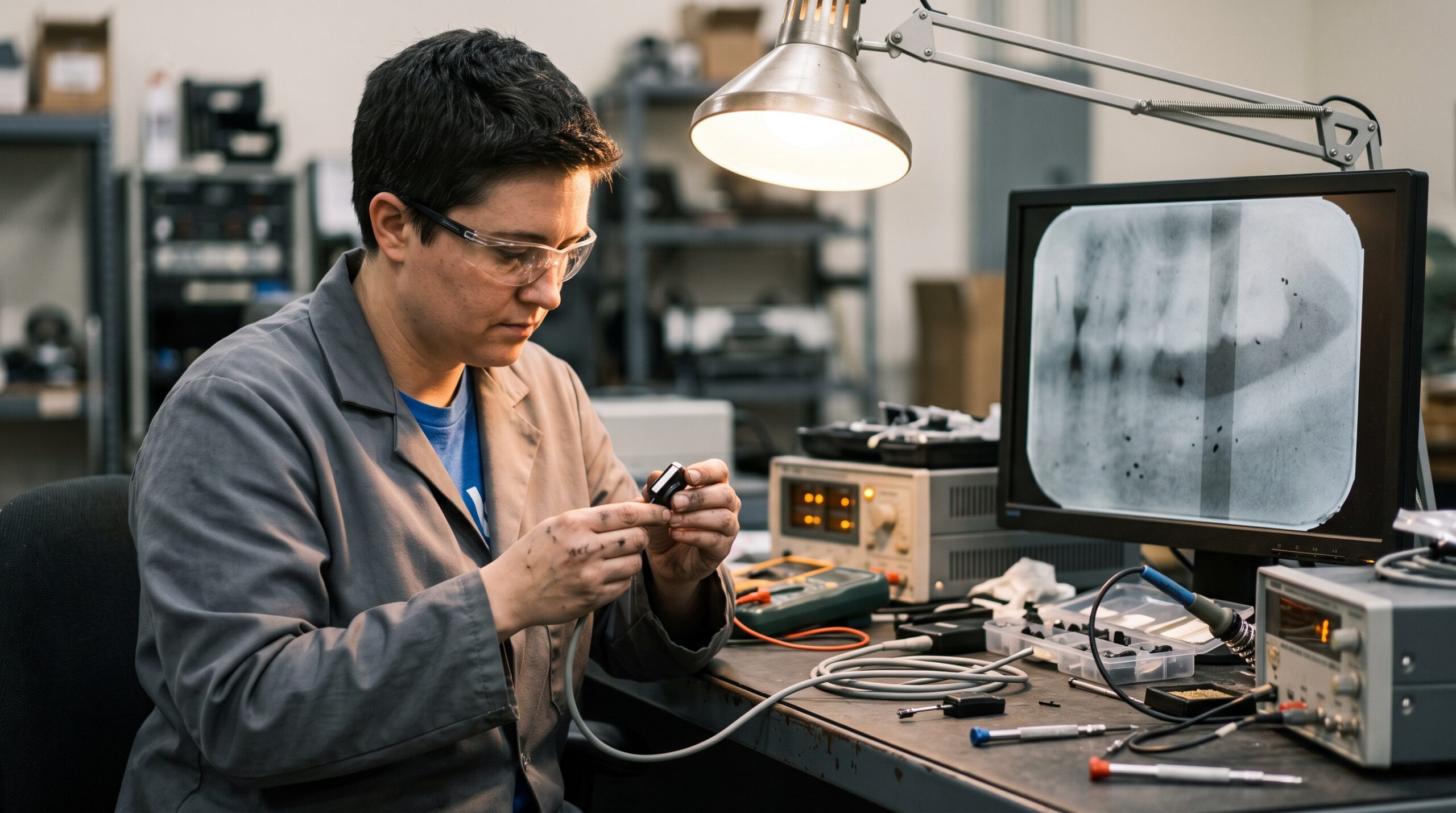
The single most useful step costs nothing: capture two or three test images and look at the defect carefully before you reach for a screwdriver or a replacement quote. Image-quality faults are not random. Each type of failure leaves a characteristic signature, and the signature tells you where the problem sits.
Work through three quick questions. First, is the defect in the same place on every image, or does it move? A fault fixed to one location is a hardware problem in that region of the sensor; a defect that moves with the anatomy is a positioning or software issue, not a sensor fault. Second, is it a point, a line, or an area? Points suggest individual pixels; lines suggest a readout row or column; areas suggest the scintillator or optical layer. Third, does it appear on a blank exposure with no tooth in the beam? If the defect survives a clean flat-field shot, it is the sensor talking, not the anatomy.
Dead and stuck pixels: the fixed points
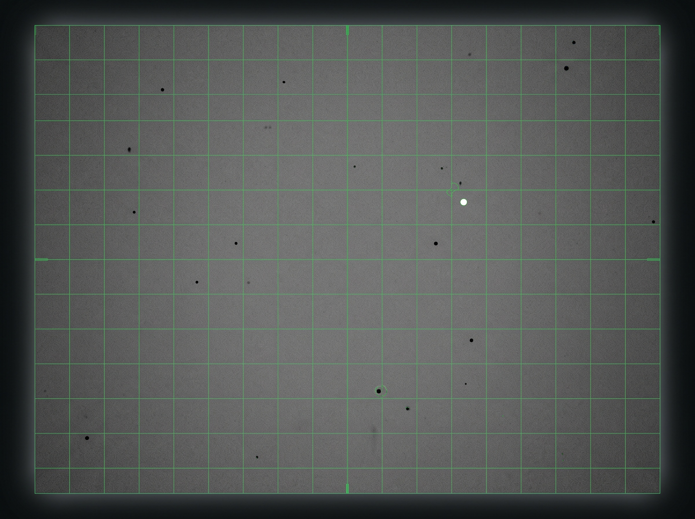
The most common fixed-point fault is a dead or stuck pixel. A dead pixel reads no signal and shows as a permanent black dot in the same spot on every image. A stuck pixel reads maximum signal and shows as a bright white dot. To confirm, take a flat-field exposure: expose the sensor to a uniform, low dose with nothing in the beam and a little distance from the tube, so the whole active area receives even radiation. On a healthy sensor you get a smooth grey field. Dead pixels punch black holes in it; stuck pixels leave bright pinpoints.
A handful of isolated bad pixels is normal and expected even on new sensors, and every quality sensor ships with a defect map that tells the software to interpolate over them. The concern is a growing count, or clusters. If a previously clean sensor is accumulating new dead pixels over weeks, or if bad pixels are grouping into a patch large enough to obscure diagnostic detail, the pixel-correction map can no longer hide it. Rerunning the manufacturer’s bad-pixel calibration will often re-map new single defects and restore a clean image. When clusters keep spreading despite recalibration, the photodiode array itself is degrading, and that is not a field repair.
Ghosting and image lag: charge that will not clear
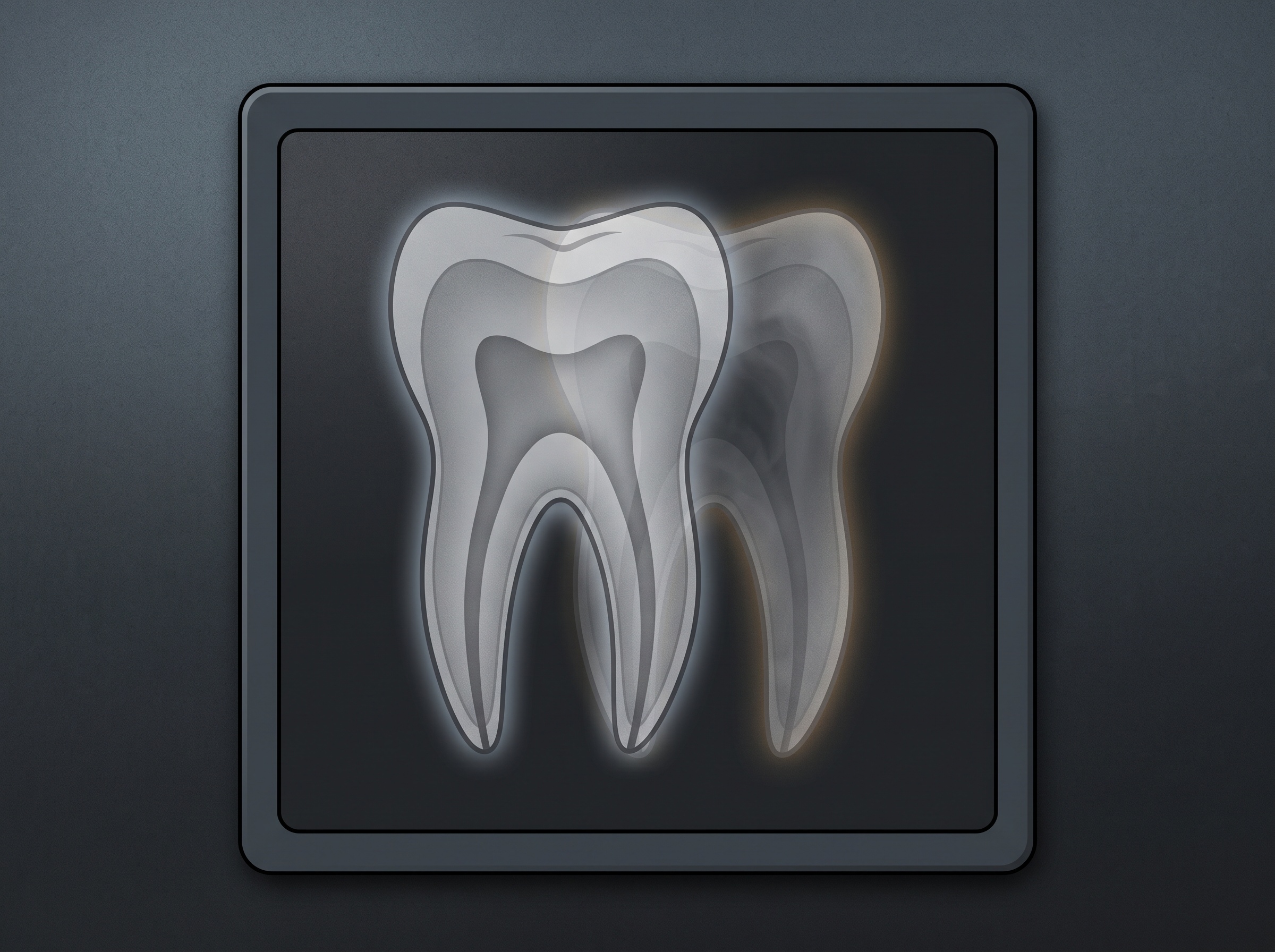
Ghosting is one of the more alarming artifacts because it looks like the sensor is haunted: a faint outline of the previous exposure appears behind the current one. The cause is residual charge. After an exposure, the sensor must fully read out and reset every pixel before the next capture. When some charge lingers, called image lag, it bleeds into the following frame as a ghost.
Before condemning the hardware, rule out workflow. Firing exposures faster than the software’s reset cycle allows, or a driver that is not clearing the buffer between captures, can both mimic a hardware ghost. Update the acquisition software and driver, and deliberately slow the capture cadence to confirm. If ghosting persists at a normal pace with current software, the reset circuitry or the photodiode array is holding charge, and the sensor is on its way out. Consistent, worsening lag is a reliable end-of-life indicator.
Banding and fixed-pattern noise: the readout electronics
Straight lines are the language of the readout chain. A digital sensor reads its pixels out in rows and columns through amplifiers and an analog-to-digital converter. When one of those channels drifts or fails, you get banding: regular light or dark stripes, or a repeating grid, laid over the image. Because the pattern is tied to the electronics rather than the dose, it is called fixed-pattern noise, and it also shows up cleanly on a flat-field test.
Some banding is correctable. Sensors rely on an offset-and-gain calibration (a dark-frame and flat-field reference) to normalize channel-to-channel variation. If that calibration has drifted or become corrupted, banding creeps in, and a fresh calibration wipes it out. This is always worth trying first because it is free and frequently works. If banding returns immediately after a good calibration, or if a single hard stripe refuses to normalize, a readout channel has genuinely failed and the fault is in the sensor’s electronics.
Scintillator and fiber-optic degradation: the cloudy areas
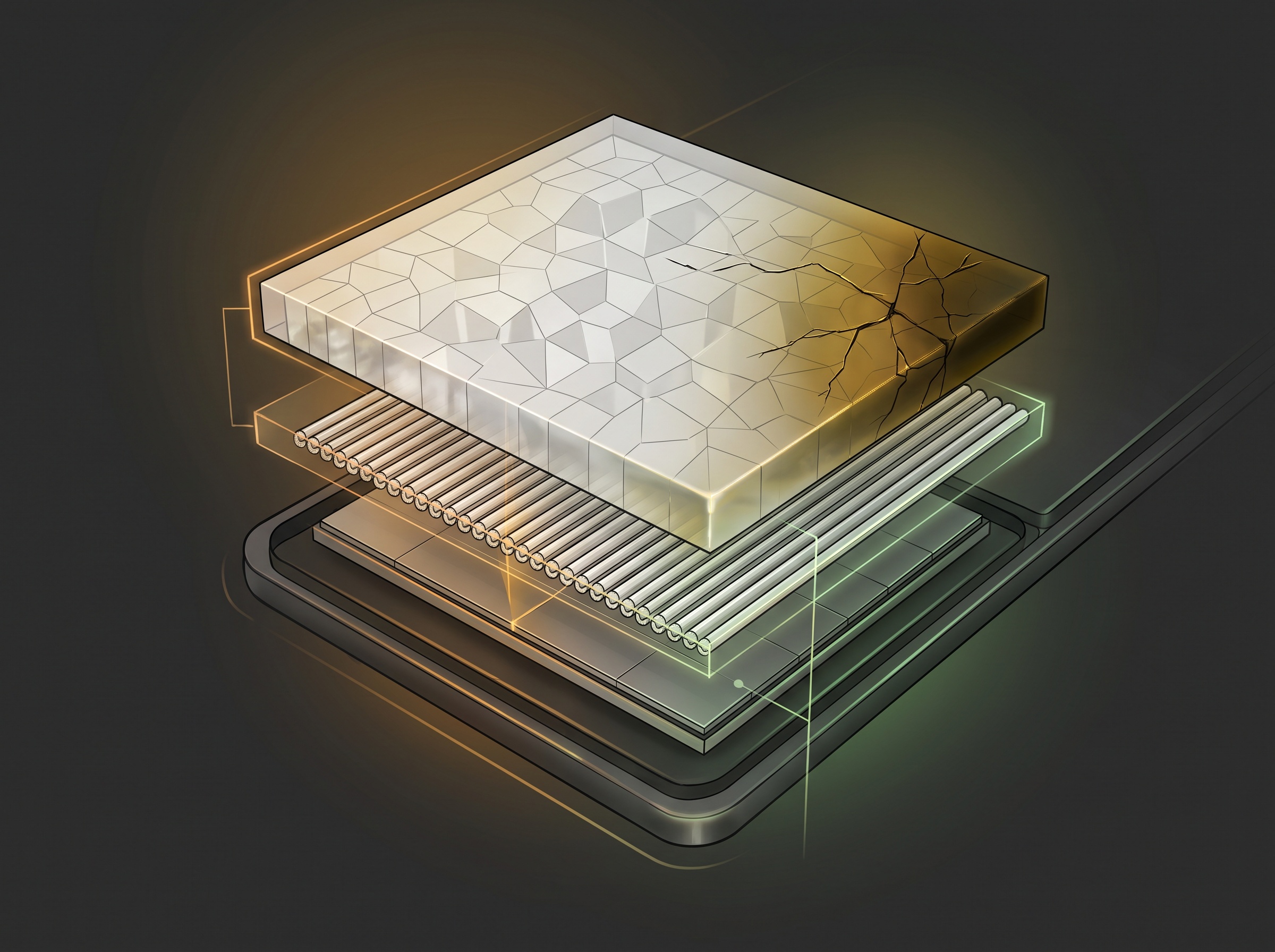
Area defects, cloudy patches, hazy corners, or a general loss of sharpness that no software setting recovers, point to the optical stack. Most intraoral sensors convert X-rays to light in a scintillator layer, funnel that light through a fiber-optic plate, and detect it on a silicon photodiode array. Physical trauma is the usual culprit here: a dropped sensor, a hard bite, or a bent housing can crack the scintillator or delaminate the fiber-optic bond. The result is a permanent cloudy or dark region exactly where the damage sits.
Moisture intrusion from a compromised seal causes the same class of symptom, often as a spreading haze. None of this is repairable in the field, and it is important to recognize it early so you stop cleaning a sensor that has an internal fault rather than a dirty surface. A telltale sign is that the cloudy area stays put on the flat-field image and never wipes away with a disinfectant pass.
Rule out the cheap causes before you condemn the sensor
Before you quote a replacement, close the loop on the causes that cost nothing to fix. Reseat and swap the cable and try a different, known-good USB port; even though these are connectivity issues, a marginal connection can occasionally corrupt image data rather than kill it outright. Reinstall or update the imaging software and sensor driver. Rerun the manufacturer’s calibration, both the bad-pixel map and the offset-gain reference. Test the sensor on a second workstation to separate a sensor fault from a host-computer or software fault. Only when the same artifact follows the sensor across machines, survives a full recalibration, and appears on a clean flat-field exposure have you truly localized the problem to the sensor hardware.
Prevention and knowing when to retire a sensor
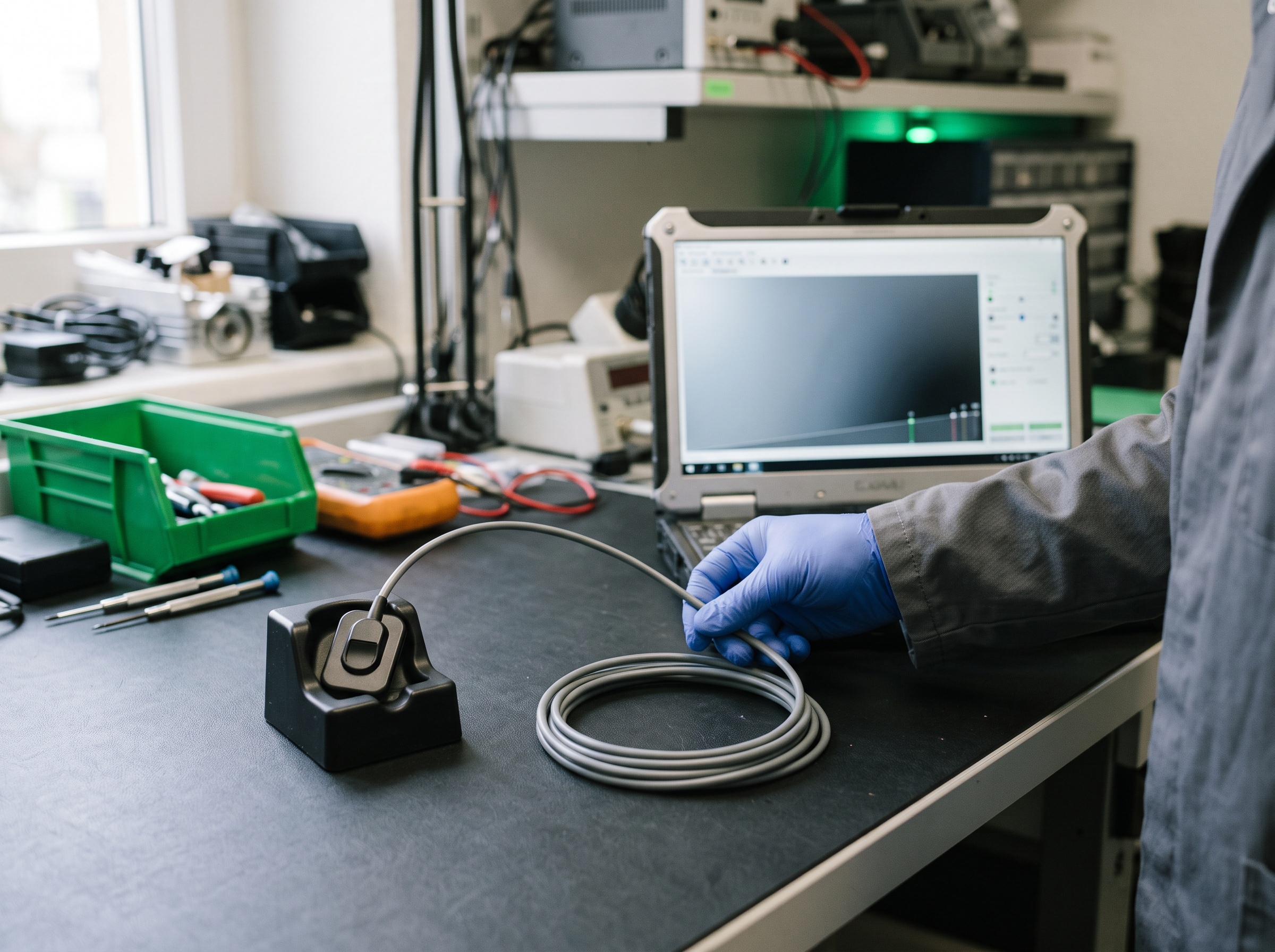
Most image-quality faults trace back to two preventable causes: physical shock and skipped calibration. Handling discipline does the heavy lifting. Use rigid sensor holders, never let the sensor dangle by its cable, coil the cable in loose loops without kinks, and store it where it cannot be dropped or crushed by a tray. Schedule the manufacturer’s flat-field and bad-pixel calibration on a regular interval rather than waiting for a complaint; catching drift early keeps banding and pixel faults invisible to the clinician.
When an artifact is confirmed to be internal, be honest about the outcome. A single new dead pixel or a drift-related band is a recalibration away from resolved. A spreading cluster of dead pixels, persistent ghosting after software updates, a hard readout stripe that will not normalize, or a cracked scintillator are all end-of-life findings. A sensor producing diagnostically compromised images is a liability, not an asset, and no amount of cleaning will bring it back. Document the flat-field evidence, retire the unit, and if you are unsure which side of that line a sensor falls on, that is exactly the point to bring in professional service for a definitive assessment before it costs a misread radiograph.