DICOM Network Integration Issues in Dental X-Ray Systems: Troubleshooting Connection and Communication Problems


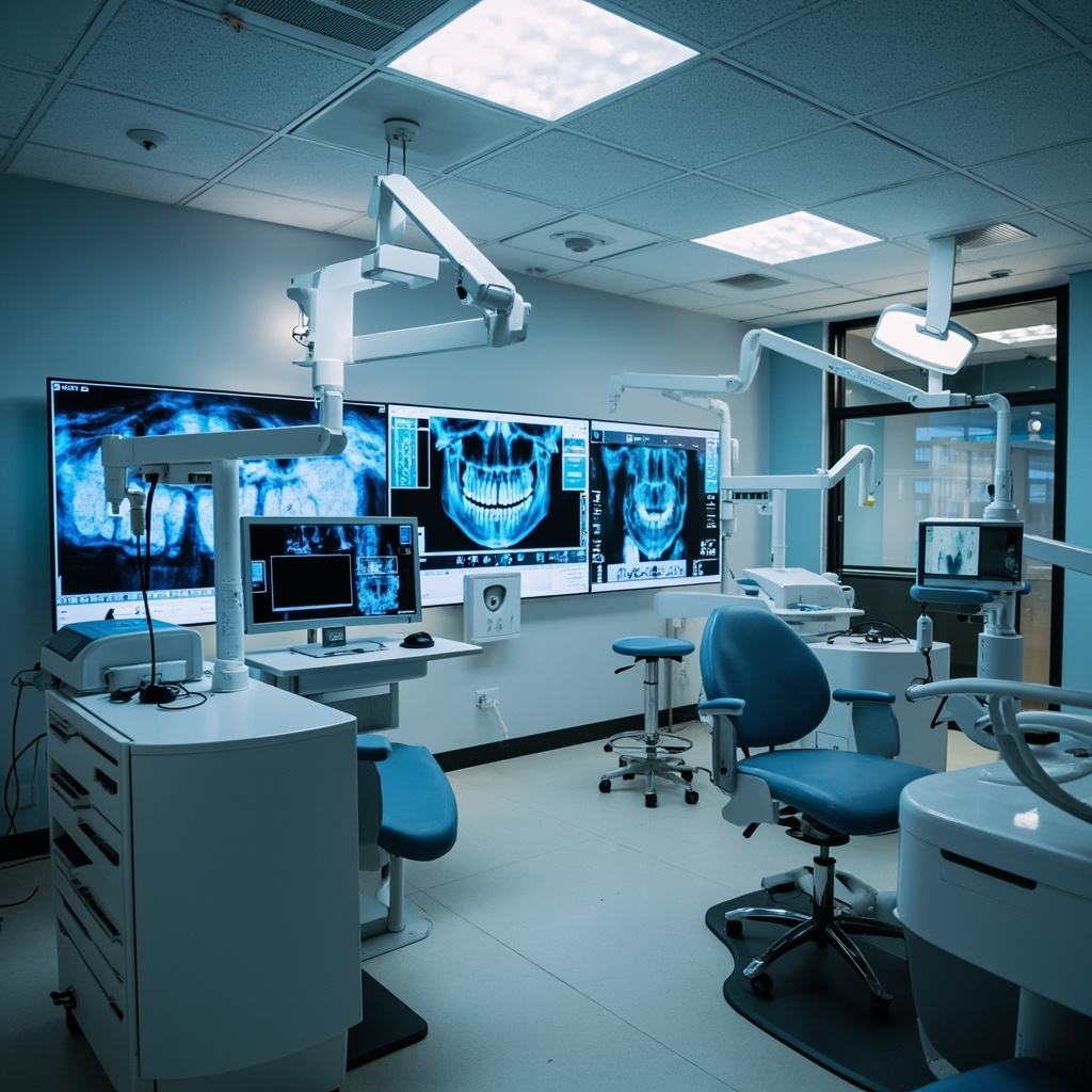
DICOM (Digital Imaging and Communications in Medicine) network integration is crucial for modern dental practices, enabling seamless communication between digital X-ray equipment and Practice Management Systems (PMS) or PACS (Picture Archiving and Communication System) servers. When DICOM connectivity fails, it disrupts workflow efficiency and can prevent proper image archiving and retrieval.

Understanding DICOM Network Architecture

DICOM networking relies on three fundamental components that must be correctly configured for successful communication:

  • IP Address: The network location of each device
  • Port Number: The communication endpoint (typically 104 or 106)
  • Application Entity (AE) Title: A unique identifier for each DICOM device

These parameters must match exactly between the sending device (X-ray equipment) and receiving device (PACS server or workstation).

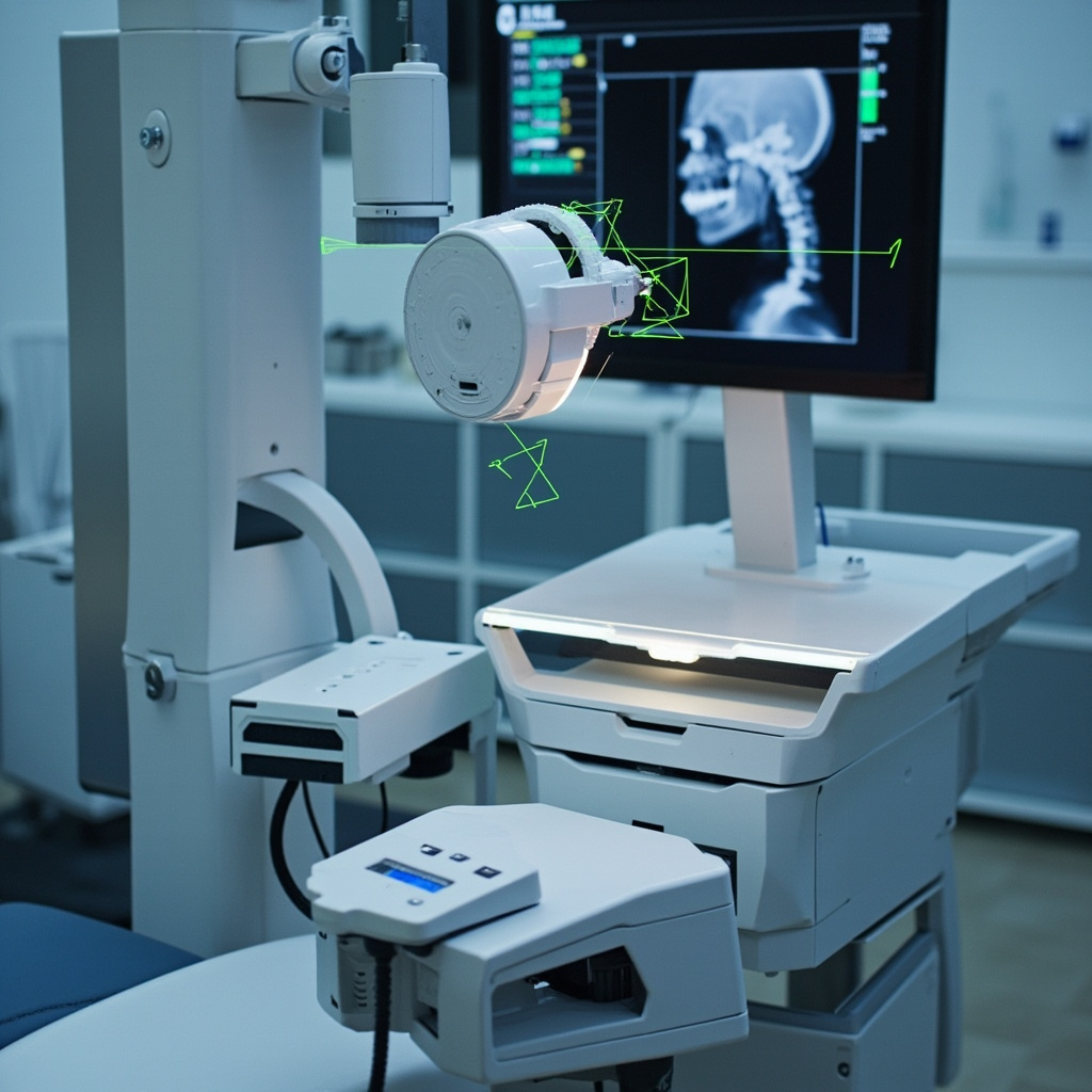
DICOM troubleshooting interface showing network diagnostics

Common DICOM Connectivity Problems

Network Layer Issues

The most frequent connectivity problems occur at the network infrastructure level:

  • Firewall Blocking: Corporate firewalls often block non-standard ports used by DICOM communication
  • Network Segmentation: X-ray equipment and PACS servers on different network subnets can’t communicate
  • IP Address Conflicts: Multiple devices assigned the same IP address cause intermittent connectivity
  • DNS Resolution Failures: Using hostnames instead of IP addresses when DNS isn’t properly configured

Configuration Mismatches

Even when network connectivity exists, configuration errors prevent successful DICOM handshakes:

  • Incorrect AE Titles: Case-sensitive AE titles must match exactly between devices
  • Port Number Mismatches: Default DICOM port 104 may be changed to 106 or custom ports
  • Transfer Syntax Issues: Incompatible image compression or transfer protocols
  • Timeout Settings: Network timeouts too short for large image transfers

Systematic Troubleshooting Approach

Step 1: Network Connectivity Testing

Begin troubleshooting with basic network connectivity tests:

  • Ping Test: Verify IP-level connectivity between X-ray equipment and PACS server
  • Telnet Port Test: Test specific DICOM port connectivity (e.g., telnet 192.168.1.100 104)
  • Network Trace: Use packet capture tools to analyze DICOM communication attempts

Step 2: DICOM Configuration Verification

Systematically verify all DICOM parameters:

  • Compare AE titles on both sending and receiving devices
  • Confirm port numbers match exactly
  • Verify IP addresses are correct and reachable
  • Check transfer syntax compatibility

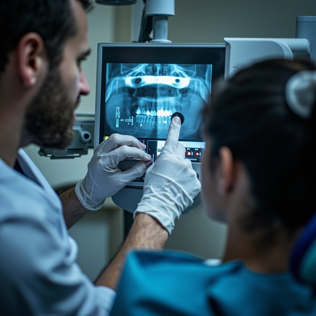
DICOM configuration panel on dental X-ray equipment

Step 3: Advanced Diagnostics

For persistent issues, employ advanced diagnostic techniques:

  • DICOM Echo Testing: Use C-ECHO commands to test basic DICOM connectivity
  • Log File Analysis: Review DICOM service logs for specific error messages
  • Protocol Analysis: Capture and analyze DICOM protocol exchanges using specialized tools

Specific Troubleshooting Scenarios

Intermittent Connection Failures

When DICOM connections work sometimes but fail unpredictably:

  • Check for IP address conflicts on the network
  • Verify network switch port configuration and duplex settings
  • Monitor network utilization during peak usage periods
  • Review DHCP lease times and IP address stability

Image Transfer Timeouts

Large image files may fail to transfer within default timeout periods:

  • Increase network timeout values in DICOM configuration
  • Optimize network bandwidth allocation
  • Consider image compression settings to reduce file sizes
  • Verify network hardware can handle sustained data transfers

Authentication and Security Issues

Modern PACS systems may implement additional security layers:

  • Verify TLS/SSL certificate validity for secure DICOM connections
  • Check user authentication credentials
  • Review access control lists (ACLs) on PACS servers
  • Confirm compliance with security policies

Prevention and Maintenance

Regular System Monitoring

Implement proactive monitoring to prevent connectivity issues:

  • Automated Testing: Schedule regular DICOM echo tests to verify connectivity
  • Log Monitoring: Set up alerts for DICOM communication errors
  • Performance Tracking: Monitor transfer times and success rates
  • Network Health Checks: Regular verification of network infrastructure

Documentation and Change Management

Maintain comprehensive documentation of your DICOM network configuration:

  • IP address assignments and DHCP reservations
  • AE title registry for all DICOM devices
  • Port number assignments and firewall rules
  • Configuration backup procedures

Advanced Solutions

DICOM Routers and Gateways

For complex network environments, DICOM routers provide enhanced connectivity:

  • Protocol translation between different DICOM implementations
  • Load balancing across multiple PACS servers
  • Enhanced security and audit logging
  • Centralized configuration management

Cloud-Based PACS Integration

Cloud PACS solutions introduce additional connectivity considerations:

  • Internet connectivity reliability and bandwidth requirements
  • VPN configuration for secure cloud connections
  • Latency optimization for real-time image viewing
  • Backup connectivity options for redundancy

Conclusion

DICOM network integration issues in dental X-ray systems require systematic troubleshooting approaches that address both network infrastructure and DICOM-specific configuration parameters. By understanding the fundamental components of DICOM networking and following structured diagnostic procedures, technicians can quickly identify and resolve connectivity problems that disrupt clinical workflows.

Regular monitoring, comprehensive documentation, and proactive maintenance help prevent connectivity issues before they impact patient care. As dental practices increasingly rely on digital imaging workflows, maintaining robust DICOM network connectivity becomes essential for operational efficiency and regulatory compliance.

Related Reading

2024 ADA Radiation Safety Update: Lead Aprons and Thyroid Collars No Longer Recommended

The American Dental Association (ADA) made significant changes to radiation safety recommendations in February 2024, fundamentally altering how dental offices approach patient protection during X-ray procedures. The expert panel established by the ADA Council on Scientific Affairs determined that lead aprons and thyroid collars are no longer recommended for routine dental radiography.

The New ADA Position

After reviewing nearly 100 research articles, guidance documents, and regulations related to dental radiography, the ADA expert panel reached a clear conclusion: the use of lead abdominal aprons and thyroid collars during dental X-ray examinations provides no meaningful benefit to patient safety. This represents a major shift from decades of standard practice in dental offices across North America.

The recommendation applies to all forms of dental radiography, including intraoral bitewing and periapical X-rays, as well as extraoral panoramic and cone beam computed tomography (CBCT) examinations. The panel found that modern X-ray equipment and techniques have reduced radiation exposure to such low levels that additional shielding offers negligible protection while potentially compromising image quality.

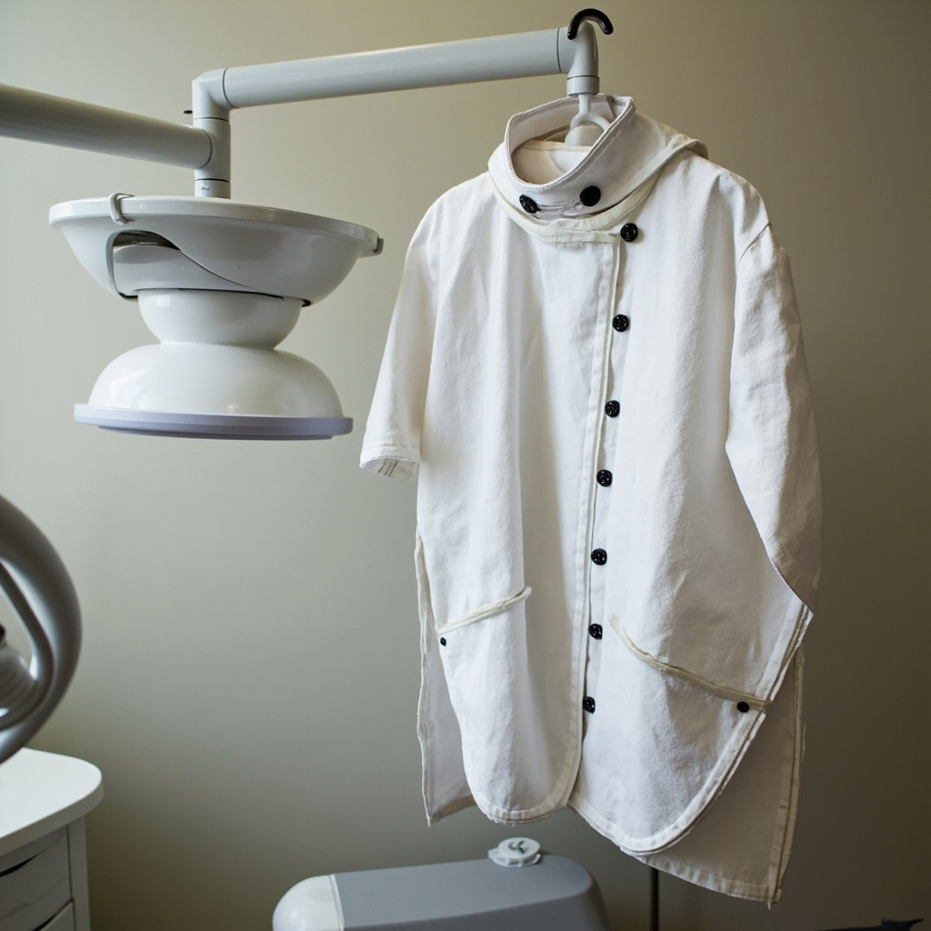
Lead apron and thyroid collar hanging in dental office

Scientific Rationale Behind the Change

The decision was based on several key factors that have evolved since lead shielding became standard practice:

  • Dramatically reduced radiation doses: Modern digital sensors and optimized exposure parameters have reduced patient radiation exposure by up to 90% compared to traditional film-based systems.
  • Improved collimation: Contemporary X-ray units feature precise beam collimation that limits radiation to the area of diagnostic interest, minimizing scatter radiation.
  • Digital image processing: Advanced image enhancement eliminates the need for retakes due to positioning errors or exposure issues.
  • Evidence-based risk assessment: Current research shows the radiation doses from dental X-rays are so low that additional protection provides no measurable health benefit.

Dr. Raymond Cohlmia, Executive Director of the ADA, emphasized that “the radiation exposure from dental X-rays is incredibly small, and the additional protection from lead aprons and thyroid collars is essentially zero.” The panel’s analysis revealed that the doses involved are comparable to background radiation exposure from natural sources.

Implementation Challenges and State Variations

While the ADA has issued clear guidance, implementation varies significantly across jurisdictions. Some states maintain regulatory requirements that conflict with the new recommendations, creating compliance challenges for dental practices.

California’s Position: California law continues to require lead or lead-equivalent aprons covering reproductive organs for all patients undergoing dental X-ray examinations, including pregnant patients. The California Dental Association acknowledges the ADA’s updated stance but notes that state law supersedes professional recommendations until regulatory changes are implemented.

International Perspectives: The International Atomic Energy Agency (IAEA) maintains different guidance, still recommending thyroid collars “where the thyroid may be exposed to the main beam or to a considerable amount of scatter radiation.” This creates additional complexity for practices serving international patients or following global standards.

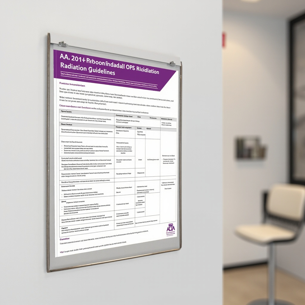
ADA radiation safety guidelines and compliance documentation

Practical Implications for Dental Practices

The transition away from lead shielding requires careful planning and staff education:

Staff Training Requirements

  • Update radiation safety protocols and documentation
  • Train team members on the scientific rationale for the change
  • Develop patient communication strategies to address concerns
  • Review and update office policy manuals

Patient Communication

Many patients expect to receive lead aprons during X-ray procedures, having been conditioned by decades of standard practice. Dental teams must be prepared to explain the scientific basis for the change and reassure patients about the safety of modern digital radiography. Clear communication about radiation dose comparisons can help patients understand that dental X-rays pose minimal risk.

Documentation and Liability

Practices should document their adherence to current ADA guidelines while ensuring compliance with applicable state regulations. This may require maintaining lead shielding for jurisdictions where it remains legally mandated while following ADA recommendations where permissible.

Quality Assurance and Alternative Safety Measures

With the removal of lead shielding, other radiation safety principles become even more critical:

  • ALARA Principle: As Low As Reasonably Achievable exposure times remain the foundation of radiation safety
  • Proper Collimation: Ensuring X-ray beams are precisely limited to diagnostic areas
  • Regular Equipment Calibration: Maintaining optimal exposure parameters and image quality
  • Digital Sensor Maintenance: Proper care and calibration of digital receptors
  • Staff Training: Ongoing education on positioning techniques and exposure optimization

These measures provide far greater radiation protection benefits than lead shielding while ensuring optimal diagnostic image quality.

Looking Forward

The 2024 ADA radiation safety update reflects the evolution of dental technology and evidence-based practice. As digital radiography continues advancing and exposure doses decrease further, the focus shifts from physical barriers to optimized techniques and equipment maintenance.

Dental practices should stay informed about regulatory changes in their jurisdiction while maintaining compliance with the highest applicable safety standards. Regular review of radiation safety protocols ensures patient protection while embracing the benefits of modern dental imaging technology.

The transition away from lead shielding represents a significant milestone in dental radiology, demonstrating how scientific evidence can guide practice improvements that benefit both patient care and operational efficiency.

Related Reading

kVp and mAs Optimization in Dental X-Ray Systems: Essential Exposure Parameter Settings Guide

Proper exposure parameter optimization is critical for producing diagnostic-quality dental radiographs while minimizing patient radiation exposure. Understanding how to correctly adjust kilovolt peak (kVp) and milliampere-seconds (mAs) settings can significantly improve image quality and reduce retakes in dental practice.

Understanding kVp and mAs Fundamentals

Kilovolt peak (kVp) controls the penetrating power and energy of the X-ray beam, directly affecting image contrast and the ability to penetrate different tissue densities. Higher kVp settings produce X-rays with greater penetrating power, resulting in lower contrast but better penetration through dense structures like enamel and metallic restorations.

Milliampere-seconds (mAs) controls the quantity of X-rays produced, directly affecting image density or darkness. A 20% change in mAs is typically required to produce a visible change in image density on digital sensors.

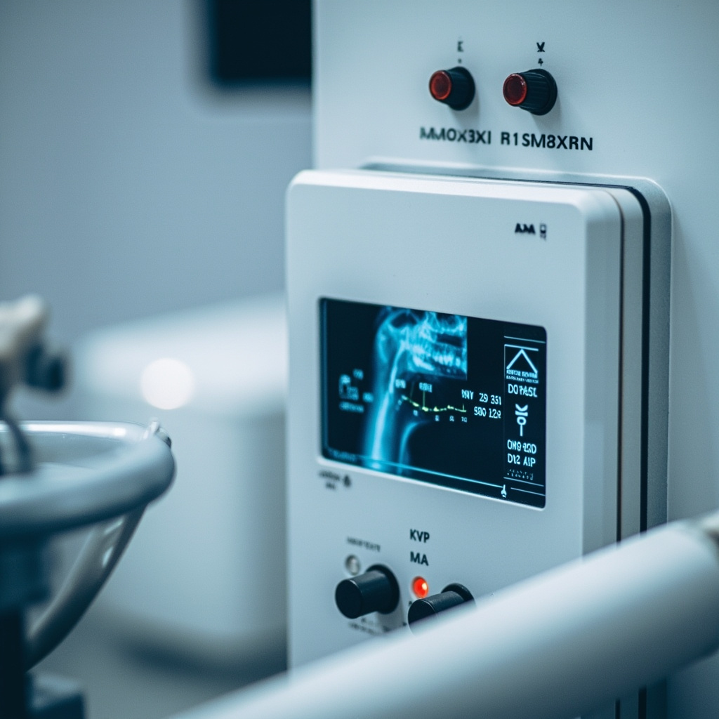
Dental X-ray exposure chart

Optimal kVp Settings for Different Clinical Scenarios

For general intraoral radiography, the optimal kVp range is between 60-70 kV. This range provides sufficient penetration for most dental structures while maintaining adequate contrast for diagnostic purposes. Patients with thicker bone density or those requiring imaging through metallic restorations may benefit from slightly higher kVp settings up to 80 kV.

When imaging pediatric patients, lower kVp settings of 60-65 kV are typically sufficient due to reduced tissue thickness. For bitewing radiographs in adults, 65-70 kVp provides optimal contrast between enamel, dentin, and carious lesions.

mAs Timing Considerations

Most modern dental X-ray units have preset mA values, making exposure time the primary variable for controlling mAs. Standard exposure times range from 0.1 to 1.6 seconds, depending on the imaging task and patient factors.

For anterior teeth, shorter exposure times (0.1-0.3 seconds) are typically adequate due to reduced tissue thickness. Posterior regions require longer exposures (0.4-0.8 seconds) to penetrate the increased bone density and tissue thickness.

The 15% Rule and Exposure Compensation

The 15% rule is a fundamental principle in radiographic exposure adjustment. When decreasing kVp by 15%, the mAs must be doubled to maintain equivalent image density. Conversely, when increasing kVp by 15%, the mAs should be halved.

This rule allows technicians to optimize image contrast while maintaining consistent exposure levels. For example, if standard settings are 70 kVp at 0.4 seconds, reducing to 60 kVp would require increasing exposure time to 0.8 seconds to maintain image density.

Comparison of dental X-ray exposures

Common Exposure Errors and Corrections

Underexposed images appear too light and lack sufficient density for diagnostic interpretation. This typically results from insufficient mAs or excessively high kVp settings. Increase exposure time or reduce kVp while compensating with increased mAs.

Overexposed images appear too dark and may obscure fine anatomical details. Reduce exposure time or increase kVp while reducing mAs accordingly. Digital sensors are more forgiving of overexposure than traditional film but optimal exposure still produces the best image quality.

Patient-Specific Adjustments

Large or muscular patients require increased exposure parameters, typically 25-50% more mAs than standard settings. Elderly patients with osteoporotic bone may require reduced exposure to prevent overexposure.

Patients with extensive metallic restorations may benefit from slightly increased kVp (75-80 kV) to improve penetration, with corresponding mAs adjustments to maintain proper density.

Quality Assurance Testing

Regular calibration of exposure parameters ensures consistent image quality and accurate exposure delivery. Annual testing should verify that actual kVp and mAs values match the control panel settings within acceptable tolerances.

Timer accuracy testing should confirm that exposure times correspond correctly to control panel selections. Digital imaging systems should be regularly calibrated to ensure optimal sensor response across the full range of exposure parameters.

Implementing standardized exposure protocols based on patient size, anatomical region, and clinical indication helps ensure consistent results and minimizes the need for retakes due to improper exposure selection.

Related Reading

Digital X-Ray Sensor Dead Pixels and Hot Pixels: Troubleshooting and Repair Guide

Digital X-ray sensors are critical components in modern dental imaging, but like all electronic devices, they can develop pixel defects over time. Dead pixels and hot pixels represent two of the most common sensor failures that can significantly impact image quality and diagnostic accuracy. Understanding these defects and their solutions is essential for maintaining optimal X-ray performance.

Understanding Pixel Defects in Digital X-Ray Sensors

Modern dental X-ray sensors use either CCD (Charge-Coupled Device) or CMOS (Complementary Metal-Oxide-Semiconductor) technology. Both sensor types contain millions of individual pixels that convert X-ray photons into electrical signals. When these pixels malfunction, they create visible artifacts in the resulting images.

Dead pixels appear as consistently black spots in X-ray images. These pixels fail to respond to X-ray exposure and remain at zero signal regardless of the radiation intensity. Hot pixels manifest as consistently white or bright spots, remaining at maximum signal output even without X-ray exposure.

Technician examining digital X-ray sensor

Common Causes of Pixel Defects

Several factors contribute to pixel degradation in digital X-ray sensors:

  • Radiation damage: Prolonged exposure to X-rays can damage semiconductor structures within individual pixels
  • Manufacturing defects: Some pixels may be faulty from production but only become apparent after extended use
  • Physical trauma: Drops, impacts, or excessive pressure can damage pixel arrays
  • Thermal stress: Temperature fluctuations during operation or storage can affect pixel integrity
  • Age-related degradation: Normal wear over time causes gradual pixel failure in older sensors

Detection and Diagnostic Methods

Regular quality assurance testing helps identify pixel defects before they impact clinical imaging:

  • Dark field imaging (no X-ray exposure) reveals hot pixels as bright spots
  • Flat field imaging (uniform X-ray exposure) shows dead pixels as dark spots
  • Pixel mapping software can automatically detect and catalog defective pixels
  • Visual inspection of clinical images for recurring artifacts in consistent locations

Troubleshooting Pixel Defects

When pixel defects are discovered, several troubleshooting steps can help determine the severity and potential solutions:

X-ray image showing pixel defects

Software-Based Solutions

Modern X-ray imaging software includes pixel defect correction capabilities:

  • Dead pixel interpolation: Software calculates missing pixel values based on surrounding pixels
  • Hot pixel suppression: Algorithms detect and correct consistently bright pixels
  • Pixel mapping updates: Regular calibration updates the sensor’s defect map
  • Noise reduction filters: Advanced filtering can minimize the visual impact of minor pixel defects

Hardware Repair Options

When software corrections aren’t sufficient, hardware intervention may be necessary:

  • Sensor recalibration: Professional recalibration can sometimes restore pixel functionality
  • Component replacement: In severe cases, sensor array replacement may be required
  • Professional repair services: Specialized technicians can perform micro-level repairs on high-value sensors
  • Warranty considerations: Check if pixel defects are covered under manufacturer warranty

Prevention and Maintenance

Proper sensor care significantly reduces the likelihood of pixel defects:

  • Use protective covers during clinical procedures
  • Avoid excessive pressure when positioning sensors
  • Store sensors in appropriate temperature and humidity conditions
  • Implement regular quality assurance testing protocols
  • Train staff on proper handling techniques

When to Replace vs. Repair

The decision between repair and replacement depends on several factors:

  • Number of defective pixels: More than 5-10 defects typically warrant replacement
  • Location of defects: Central defects impact diagnosis more than edge defects
  • Sensor age: Older sensors may develop additional defects quickly
  • Repair costs: Compare repair expenses against new sensor investment
  • Downtime considerations: Factor in practice disruption during repair periods

Conclusion

Dead pixels and hot pixels in digital X-ray sensors are inevitable challenges in modern dental imaging. However, with proper understanding, regular monitoring, and appropriate maintenance protocols, their impact on diagnostic quality can be minimized. When pixel defects do occur, a combination of software corrections and professional repair services can often restore sensor functionality. Regular quality assurance testing remains the cornerstone of early detection and effective management of pixel defects in dental X-ray systems.

Related Reading

Dental X-Ray Tube Replacement and Upgrade Procedures: Complete Installation Guide

Dental X-ray tube replacement is a critical maintenance procedure that ensures optimal imaging quality and extends equipment lifespan. This comprehensive guide provides essential information for dental practice managers, service technicians, and equipment specialists on proper tube replacement and upgrade procedures.

When X-Ray Tube Replacement Becomes Necessary

X-ray tubes have finite lifespans, typically ranging from 5-10 years depending on usage patterns and maintenance quality. Key indicators that replacement is needed include:

  • Decreased Image Quality: Gradual reduction in contrast and sharpness despite proper technique settings
  • Extended Exposure Times: Longer exposure requirements to achieve adequate image density
  • Filament Burnout: Complete failure of the tungsten filament, preventing X-ray production
  • Anode Wear: Pitting or cracking of the anode target surface affecting beam quality
  • Housing Leakage: Radiation leakage exceeding regulatory limits during routine testing

Regular performance monitoring and annual quality assurance testing help identify degradation before complete failure occurs.

Compatibility and Selection Considerations

X-ray tube components and installation hardware

Proper tube selection requires careful attention to compatibility factors:

Electrical Specifications

  • Voltage Rating: Match the kVp range (typically 60-70 kVp for intraoral, 60-90 kVp for panoramic)
  • Current Rating: Ensure adequate mA capacity for required exposure times
  • Focal Spot Size: Consider image resolution requirements (0.4-1.0mm typical)

Physical Compatibility

  • Housing Dimensions: Verify tube head housing can accommodate new tube assembly
  • Mounting Configuration: Check bolt patterns and mechanical interfaces
  • Cooling Requirements: Ensure adequate heat dissipation capacity
  • Cable Connections: Verify high-voltage cable compatibility and insulation ratings

Always consult manufacturer specifications and consider upgrading the entire tube head assembly if the existing housing cannot accommodate modern tube designs.

Safety Requirements and Preparation

X-ray tube replacement involves high-voltage components and radiation safety considerations:

Required Safety Equipment

  • High-voltage safety gloves rated for equipment voltage levels
  • Insulated tools and test equipment
  • Radiation survey meter for leakage testing
  • Personal dosimetry badges

Pre-Installation Steps

  • Power Isolation: Disconnect and lock out main power supply
  • Discharge Verification: Test all high-voltage components with appropriate meters
  • Documentation: Record existing settings and calibration parameters
  • Work Area Preparation: Ensure adequate lighting and workspace organization

Only qualified service technicians should perform tube replacements due to electrical hazards and regulatory requirements.

Installation Procedures

Proper installation follows manufacturer-specific procedures with common steps:

Tube Removal

  1. Remove tube head housing covers and protective barriers
  2. Disconnect high-voltage cables using proper lifting techniques
  3. Remove mounting bolts securing tube assembly to housing
  4. Carefully extract old tube, noting orientation and connection points

New Tube Installation

  1. Inspect new tube for shipping damage and verify model compatibility
  2. Position tube in housing using proper lifting equipment for heavy assemblies
  3. Secure mounting bolts to manufacturer torque specifications
  4. Reconnect high-voltage cables ensuring proper insulation and strain relief
  5. Install housing covers and radiation shielding components

Critical Installation Points

  • Cable Management: Ensure proper routing to prevent pinching or stress
  • Cooling Airflow: Verify unobstructed ventilation paths
  • Grounding: Confirm proper electrical grounding connections
  • Mechanical Alignment: Check tube positioning relative to collimator and patient positioning

Post-Installation Testing and Calibration

Professional calibration testing of dental X-ray equipment

Comprehensive testing ensures safe operation and optimal performance:

Initial Function Tests

  • Power-On Sequence: Verify normal startup and system diagnostics
  • Exposure Tests: Confirm proper X-ray production at various settings
  • Timer Accuracy: Test exposure time consistency across all available settings
  • kVp Calibration: Verify voltage output matches display settings

Safety and Leakage Testing

  • Radiation Leakage: Survey tube head housing for stray radiation
  • Beam Quality: Test half-value layer and filtration adequacy
  • Collimation Accuracy: Verify beam alignment with light field indicators
  • Patient Dose Assessment: Measure entrance dose rates for typical exposures

Image Quality Verification

  • Test Phantom Imaging: Capture standardized test images
  • Contrast Resolution: Verify ability to distinguish tissue densities
  • Spatial Resolution: Test line pair visibility and edge definition
  • Noise Assessment: Evaluate image uniformity and artifact presence

Document all test results and maintain records for regulatory compliance and warranty purposes.

Cost-Benefit Analysis and Decision Making

Tube replacement decisions involve several financial considerations:

Replacement Costs

  • Tube Assembly: $2,000-$8,000 depending on specifications
  • Labor Costs: $500-$1,500 for professional installation
  • Testing and Calibration: $300-$800 for compliance verification
  • Potential Downtime: Lost production during service period

Upgrade Opportunities

  • Improved Efficiency: Modern tubes may reduce exposure times
  • Enhanced Image Quality: Better focal spot design and filtration
  • Extended Lifespan: Advanced materials and construction techniques
  • Energy Efficiency: Reduced power consumption and heat generation

Alternative Considerations

  • Complete Unit Replacement: May be cost-effective for aging equipment
  • Refurbished Tubes: Lower-cost option for older systems
  • Preventive Maintenance: Extending current tube life through proper care

Consider total cost of ownership, including maintenance, energy consumption, and image quality requirements when making replacement decisions.

Conclusion

Dental X-ray tube replacement requires careful planning, proper safety protocols, and thorough post-installation testing. While the procedure involves significant costs and technical complexity, timely replacement ensures continued diagnostic capability and regulatory compliance.

Working with qualified service technicians and maintaining detailed documentation helps ensure successful installations and optimal equipment performance. Regular monitoring and preventive maintenance can extend tube life and provide advance warning of replacement needs.

For practices considering tube replacement, evaluate both immediate needs and long-term equipment strategies to make informed decisions that support quality patient care and operational efficiency.

Related Reading

Storage Phosphor Plate Artifacts in Dental X-Ray Imaging: Identification and Resolution Guide

Storage phosphor plates (PSP) have become essential components in digital dental radiography, offering reusable imaging solutions with excellent image quality. However, various artifacts can compromise image integrity and diagnostic accuracy. Understanding these artifacts, their causes, and resolution strategies is crucial for maintaining optimal imaging performance.

Understanding PSP Artifacts

Storage phosphor plate artifacts are unwanted image distortions that can appear on digital radiographs. These artifacts can be categorized into three main types: physical plate damage, scanning system issues, and handling-related problems. Each category presents distinct visual characteristics that require specific identification and resolution approaches.

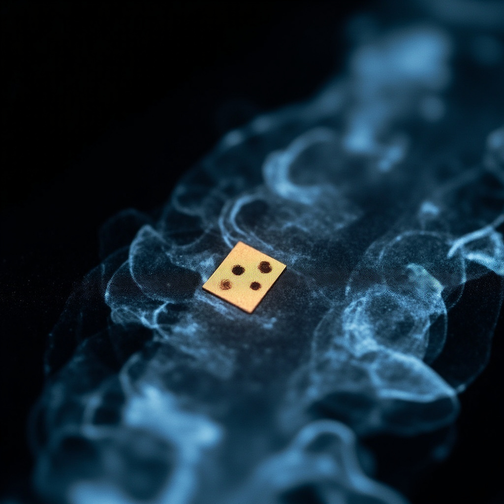
Close-up view of storage phosphor plate artifacts

Common Types of PSP Artifacts

Physical Damage Artifacts

Physical damage to PSP plates manifests as permanent marks or distortions on radiographic images. These include:

  • Scratches and Abrasions: Appear as white or dark linear marks across the image, typically caused by improper handling or contact with sharp objects
  • Creases and Bends: Result in permanent deformation lines that show as artifacts on all subsequent images
  • Edge Damage: Worn or damaged plate edges can cause border artifacts and reduced image area

Contamination Artifacts

Foreign material on PSP plates creates distinctive artifact patterns:

  • Dust and Debris: Small particles appear as white spots or specks on the final image
  • Fingerprints and Moisture: Create cloudy or smudged areas that can obscure diagnostic information
  • Chemical Contamination: Residues from cleaning solutions can cause permanent staining or altered sensitivity areas

Scanner-Related Artifacts

Issues with the PSP scanner system can introduce systematic artifacts:

  • Dirty Scanner Components: Dust or debris in the scanner creates repeating line patterns
  • Calibration Drift: Improper scanner calibration results in density variations or color shifts
  • Mechanical Wear: Worn transport mechanisms can cause irregular spacing or speed variations

Artifact Prevention Strategies

Preventing PSP artifacts requires systematic attention to handling, storage, and maintenance protocols. Proper preventive measures significantly reduce artifact occurrence and extend plate lifespan.

Quality control procedures for storage phosphor plates

Proper Handling Techniques

Implement standardized handling procedures to minimize physical damage:

  • Use clean, dry hands or appropriate gloves when handling plates
  • Hold plates by edges only, avoiding contact with the active imaging surface
  • Store plates in protective sleeves or containers when not in use
  • Avoid stacking plates without adequate protection between surfaces

Environmental Controls

Maintain appropriate environmental conditions:

  • Control humidity levels to prevent moisture-related artifacts
  • Minimize dust exposure through proper air filtration
  • Maintain stable temperature conditions to prevent thermal stress
  • Implement clean room practices in imaging areas

Resolution and Troubleshooting

Immediate Response Protocols

When artifacts are detected, immediate assessment and action are essential:

  • Identify the Artifact Type: Determine whether the issue is physical damage, contamination, or scanner-related
  • Isolate Affected Equipment: Remove damaged plates from service and identify problematic scanner components
  • Document Findings: Record artifact patterns, affected equipment, and suspected causes

Cleaning and Restoration Procedures

For contamination-related artifacts:

  • Use manufacturer-approved cleaning solutions and techniques
  • Employ lint-free cloths and gentle circular motions
  • Ensure complete drying before returning plates to service
  • Test cleaned plates with quality assurance exposures

Scanner Maintenance and Calibration

Regular scanner maintenance prevents systematic artifacts:

  • Clean scanner transport mechanisms and optical components
  • Perform regular calibration checks using reference standards
  • Replace worn components according to manufacturer schedules
  • Monitor scanner performance through quality control testing

Quality Assurance Testing

Implement comprehensive quality assurance programs to detect artifacts early:

  • Daily Testing: Perform basic functionality checks and artifact screening
  • Weekly Assessment: Conduct detailed plate inspections and scanner calibration verification
  • Monthly Evaluation: Complete comprehensive quality assurance testing including exposure consistency and artifact assessment

Cost-Benefit Considerations

Effective artifact management provides significant economic benefits:

  • Reduced retake rates and associated radiation exposure
  • Extended equipment lifespan through proper maintenance
  • Improved diagnostic accuracy and patient satisfaction
  • Decreased downtime and productivity losses

Conclusion

Storage phosphor plate artifacts in dental X-ray imaging require systematic identification, prevention, and resolution strategies. By implementing proper handling procedures, maintaining environmental controls, and establishing comprehensive quality assurance programs, dental practices can minimize artifact occurrence and maintain optimal imaging performance. Regular training and protocol adherence ensure consistent results and maximize the benefits of PSP technology in modern dental radiography.

Related Reading

Automatic Exposure Control (AEC) Sensor Calibration and Troubleshooting in Dental X-Ray Equipment

Automatic Exposure Control (AEC) systems are critical components in modern dental X-ray equipment, ensuring consistent image quality while minimizing radiation exposure to patients. However, when AEC sensors fall out of calibration or malfunction, they can significantly impact diagnostic image quality and workflow efficiency. This comprehensive guide covers the essential calibration procedures and troubleshooting techniques for dental AEC systems.

Understanding AEC Photocell Sensor Operation

AEC systems function by measuring the amount of radiation transmitted through the patient using specialized photocell sensors or ionization chambers. These sensors convert radiation into electrical signals that terminate the X-ray exposure when a predetermined threshold is reached. The calibration of these sensors determines the optical density and contrast characteristics of the final radiographic image.

Dental X-ray technician calibrating photocell sensor detector

Modern digital dental X-ray systems rely on precise AEC calibration to maintain consistent detector dose indicator (DDI) values and signal-to-noise ratios across varying tube potentials and patient anatomical differences.

Common AEC Calibration Issues and Symptoms

Several indicators suggest that your AEC system requires recalibration or maintenance:

  • Inconsistent image density – Images appear too light or too dark despite proper technique selection
  • Excessive retakes – Higher frequency of repeat exposures due to poor image quality
  • Erratic exposure times – Unpredictable variation in automatic exposure durations
  • Sensor drift – Gradual change in calibration over time, particularly noticeable with phantom testing
  • Temperature sensitivity – Performance changes with ambient temperature fluctuations

Diagnostic Testing Procedures

Begin AEC troubleshooting with systematic phantom testing using standardized acrylic or aluminum phantoms. Document baseline measurements and compare against manufacturer specifications to identify calibration drift patterns.

Step-by-Step Calibration Protocol

Professional AEC calibration requires specialized test equipment and should be performed by qualified service technicians. However, understanding the process helps dental professionals recognize calibration issues:

Pre-calibration preparation:

  • Ensure X-ray tube warmup according to manufacturer specifications
  • Verify stable line voltage and temperature conditions
  • Clean photocell sensors and remove any debris or contamination
  • Check mechanical alignment of sensors relative to the X-ray beam

Close-up view of dental X-ray automatic exposure control circuit board and electronics

Calibration sequence:

  1. Access service mode through manufacturer-specific procedures
  2. Set baseline reference values using standardized phantoms
  3. Adjust sensitivity curves for different kV settings
  4. Verify linearity across the full operating range
  5. Test backup timer functionality and failsafe systems
  6. Document all calibration values and settings

Preventive Maintenance Strategies

Regular maintenance prevents many AEC calibration issues before they affect image quality:

  • Monthly cleaning – Gently clean sensor surfaces with manufacturer-approved solutions
  • Quarterly phantom testing – Document performance trends using consistent test protocols
  • Annual professional calibration – Schedule comprehensive service including electronic adjustments
  • Environmental monitoring – Maintain stable temperature and humidity in equipment areas

When to Contact Service Support

Contact qualified service technicians immediately if you observe:

  • Phantom test results outside acceptable tolerance ranges
  • Intermittent sensor failures or backup timer activation
  • Visible damage to sensor assemblies or connecting cables
  • Error codes related to exposure control systems

Advanced Troubleshooting Considerations

Modern digital radiography systems present unique challenges for AEC calibration due to the wide dynamic range of digital detectors compared to conventional film systems. Calibration must account for detector characteristics, image processing algorithms, and display monitor settings that affect perceived image quality.

Additionally, facilities using multiple detector types (direct digital sensors, phosphor plates, film) may require separate AEC calibration profiles to optimize image quality for each receptor technology.

Proper AEC sensor calibration ensures consistent, high-quality diagnostic images while maintaining radiation protection principles. Regular monitoring, preventive maintenance, and professional calibration services are essential components of any comprehensive dental X-ray quality assurance program.

Related Reading

Motion Blur and Double Exposure Artifacts in Dental X-Ray Imaging: Prevention and Troubleshooting Guide

Motion blur and double exposure artifacts represent two of the most common image quality problems in dental radiography. These technical errors can significantly compromise diagnostic accuracy and require immediate correction to maintain clinical standards.

Understanding Motion Blur Artifacts

Motion blur occurs when the patient, X-ray tube head, or image receptor moves during the exposure time. This movement creates characteristic blurred edges and unclear anatomical details that can mask important diagnostic information.

Primary Causes of Motion Blur

  • Patient Movement: Involuntary head or body motion during exposure
  • Inadequate Patient Stabilization: Loose headrests or improper bite block placement
  • Equipment Vibration: Unstable tube head positioning or mechanical issues
  • Prolonged Exposure Times: Extended exposure duration increasing movement probability

Clinical research indicates that even minimal movement of 0.5mm during exposure can create noticeable blur artifacts, particularly affecting fine anatomical structures like the periodontal ligament space and lamina dura.

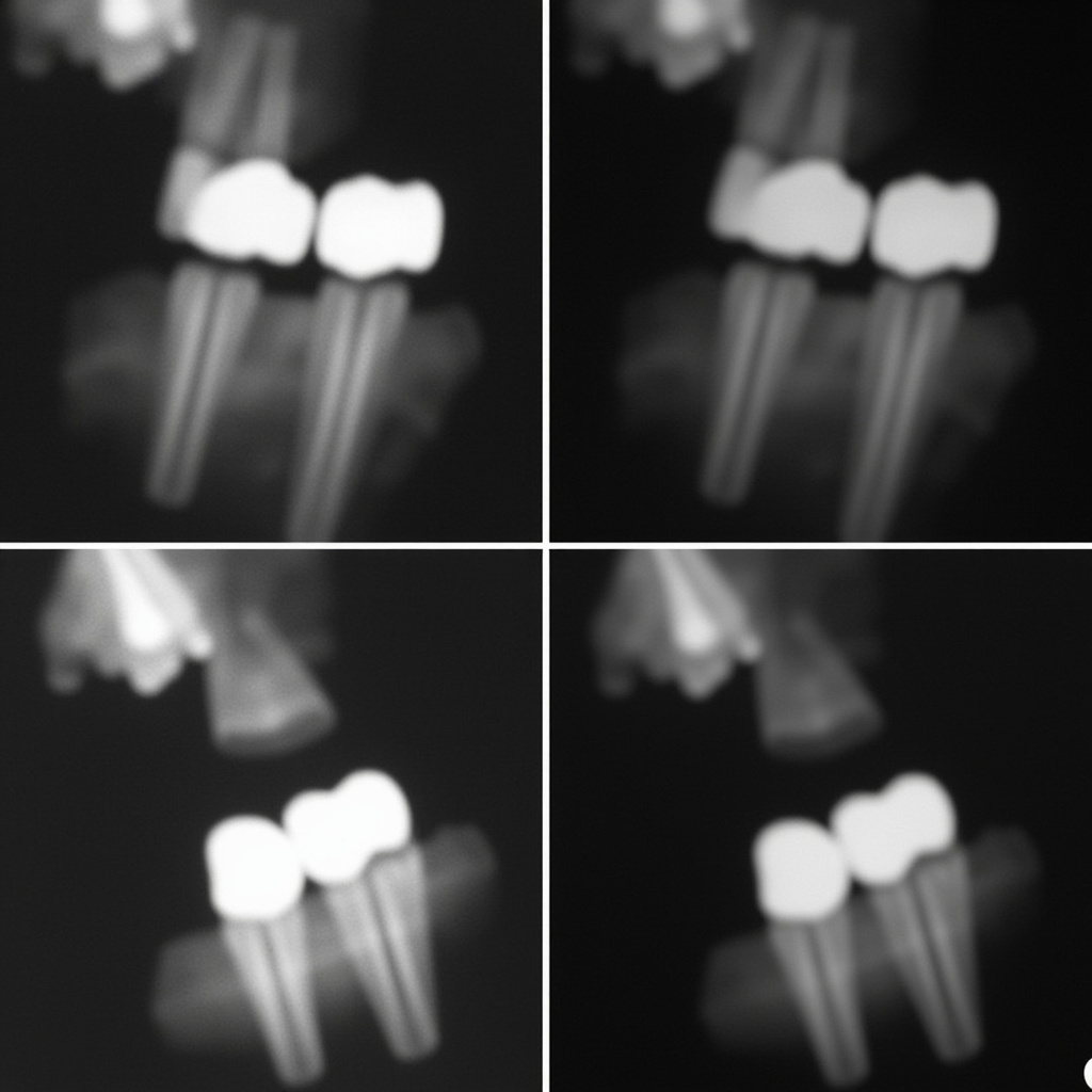
Double exposure artifact showing overlapping ghosted dental structures

Double Exposure Artifacts: Recognition and Prevention

Double exposure artifacts occur when the same image receptor is inadvertently exposed twice, creating overlapping ghosted images. This error is more common with phosphor storage plates (PSP) than with digital sensors.

Identifying Double Exposure Characteristics

  • Overlapping Structures: Two identical anatomical features superimposed
  • Density Variations: Areas of excessive radiopacity from double radiation exposure
  • Ghost Images: Faint secondary images offset from primary structures
  • Geometric Distortion: Misaligned anatomical relationships

Double exposures most commonly result from PSP plate reuse without proper erasure, accidental re-exposure of used receptors, or software errors in digital imaging systems.

Proper patient positioning technique demonstrating stabilization methods to prevent motion blur

Technical Solutions and Prevention Protocols

Motion Blur Prevention Strategies

Implementing proper patient positioning and stabilization techniques significantly reduces motion blur incidents:

  • Headrest Optimization: Adjust headrest to provide three-point contact stabilization
  • Bite Block Selection: Use appropriate bite block size and positioning for receptor stability
  • Clear Communication: Provide specific breath-hold instructions with countdown timing
  • Exposure Time Minimization: Use optimal technique factors to reduce exposure duration

Double Exposure Elimination Methods

Systematic workflow protocols prevent double exposure artifacts:

  • PSP Plate Management: Implement immediate erasure protocols after image acquisition
  • Digital Receptor Tracking: Use color-coding or labeling systems for used receptors
  • Software Integration: Enable automatic exposure logging in imaging software
  • Quality Control Checks: Review images immediately after acquisition

Diagnostic Impact and Clinical Considerations

Both motion blur and double exposure artifacts can significantly impact diagnostic accuracy. Motion blur particularly affects:

  • Periodontal bone level assessment
  • Root fracture detection
  • Caries diagnosis in interproximal areas
  • Endodontic length determination

Double exposures create false positive findings and can mask actual pathology, requiring complete retake of affected radiographs.

Equipment Maintenance and Calibration

Regular equipment maintenance prevents many artifact-causing issues. Monthly calibration should include tube head stability testing, exposure timer verification, and image receptor quality assessment.

Modern digital systems offer motion detection algorithms and exposure validation features that can alert operators to potential artifacts before image finalization.

Staff Training and Protocols

Comprehensive staff training on artifact recognition and prevention ensures consistent image quality. Regular continuing education sessions should cover new techniques and technology updates for artifact minimization.

Implementing standardized protocols for patient positioning, equipment operation, and quality control creates a systematic approach to artifact prevention and maintains diagnostic imaging standards.

Related Reading

Dental X-Ray Equipment Workflow Integration and Efficiency Optimization

Modern dental practices face increasing demands for efficiency while maintaining exceptional patient care standards. Digital X-ray equipment workflow integration has emerged as a critical factor in practice optimization, with studies showing that properly integrated systems can reduce imaging time by up to 40% while improving diagnostic accuracy.

Understanding Workflow Integration Challenges

Traditional dental X-ray workflows often involve multiple disconnected systems that create bottlenecks and inefficiencies. Common pain points include manual data entry, incompatible software platforms, and fragmented patient records that require technicians to navigate between multiple applications during a single imaging session.

The 2026 dental technology landscape demands seamless integration between X-ray hardware, practice management software, and diagnostic tools. Practices utilizing integrated workflows report significant improvements in both patient throughput and staff satisfaction.

Digital X-ray sensor positioning device with automated workflow integration

Key Components of Optimized X-Ray Workflows

Automated Patient Data Transfer

Modern dental X-ray systems should automatically populate patient information from practice management software, eliminating manual entry errors and reducing setup time. DICOM compliance ensures seamless data exchange between imaging equipment and storage systems.

Real-Time Quality Assessment

Integrated quality control systems provide immediate feedback on image quality, allowing for immediate retakes when necessary rather than discovering issues during review. This reduces patient recall appointments and improves first-pass success rates.

Streamlined Image Processing

Automated image enhancement and processing algorithms can improve diagnostic quality while reducing the time radiographers spend on manual adjustments. Advanced systems learn from user preferences to optimize processing parameters automatically.

Measuring and Improving Workflow Efficiency

Successful workflow optimization requires comprehensive metrics tracking and analysis. Key performance indicators include image acquisition time, processing duration, and integration points between systems.

Dashboard showing dental practice efficiency metrics and workflow analytics

Essential Efficiency Metrics

  • Patient throughput time: Total time from patient positioning to completed radiograph
  • System integration delays: Time lost during data transfer between systems
  • Retake rates: Percentage of images requiring additional exposures
  • Staff utilization: Optimal allocation of radiographer time and responsibilities

Implementation Best Practices

Begin workflow optimization with a comprehensive audit of current processes, identifying specific bottlenecks and integration gaps. Prioritize high-impact improvements that address the most significant time delays or error sources.

Staff training is crucial for successful implementation. Ensure all team members understand new workflows and can troubleshoot common integration issues. Regular refresher training sessions help maintain optimal efficiency levels.

Future-Proofing Your X-Ray Workflow

The dental technology landscape continues evolving rapidly. Select X-ray equipment and software platforms that support open standards and API integration to ensure compatibility with future innovations.

Cloud-based solutions offer enhanced flexibility and scalability, allowing practices to adapt workflows as patient volume grows. Consider systems that support artificial intelligence integration for automated diagnosis assistance and predictive maintenance.

Regular workflow assessments and updates ensure your practice maintains peak efficiency as technology advances and patient expectations evolve.

Related Reading

Anti-Scatter Grid Artifacts in Dental X-Ray Imaging: Diagnosis and Prevention Guide

Anti-scatter grids are essential components in dental X-ray imaging systems, designed to improve image quality by reducing scattered radiation. However, improper grid positioning, alignment issues, or equipment malfunctions can create distinctive artifacts that compromise diagnostic quality. This comprehensive guide addresses the identification, diagnosis, and prevention of grid-related artifacts in dental radiography.

Understanding Anti-Scatter Grid Function

Anti-scatter grids consist of thin lead strips separated by radiolucent material, designed to absorb scattered X-rays while allowing primary radiation to pass through. In dental imaging, grids are particularly important for extraoral radiography, panoramic systems, and CBCT imaging where scattered radiation can significantly degrade image quality.

Grid artifact patterns visible on dental X-ray display

Common Grid Artifact Patterns

Grid Line Artifacts

Grid line artifacts appear as parallel lines running across the image, typically perpendicular to the lead strips. These artifacts result from:

  • Improper grid alignment with the X-ray beam
  • Grid positioning errors relative to the imaging receptor
  • Incorrect focal distance settings
  • Grid frequency mismatch with digital detector sampling

Moiré Pattern Formation

Moiré patterns create wavy, interference patterns across the image when the grid frequency interacts with the detector pixel array. This is particularly common with digital radiography systems where the grid frequency approaches the Nyquist frequency of the detector.

Grid Cutoff Effects

Grid cutoff manifests as uneven density across the image, typically showing darkened areas where the grid has absorbed primary radiation. Common causes include:

  • Lateral decentering of the grid
  • Angular misalignment
  • Incorrect focal distance
  • Grid inversion (upside-down installation)

Diagnostic Procedures for Grid Issues

Visual Inspection Protocol

Systematic visual examination should include:

  • Grid physical condition assessment
  • Alignment verification using laser positioning systems
  • Focal distance measurement and verification
  • Grid frequency documentation and comparison to detector specifications

Test Pattern Analysis

Regular test exposures using phantoms can reveal subtle grid artifacts before they affect clinical images. Test protocols should include:

  • Uniform field exposures to detect grid line artifacts
  • Edge response testing for alignment verification
  • Density uniformity assessment across the image field

Technician adjusting grid positioning mechanism

Prevention and Correction Strategies

Proper Grid Installation

Correct grid installation requires precise attention to:

  • Grid orientation relative to the X-ray tube
  • Focal distance settings matching grid specifications
  • Centering accuracy within ±1cm tolerance
  • Secure mounting to prevent movement during operation

Digital System Optimization

For digital radiography systems, grid artifact reduction involves:

  • Software-based grid line suppression algorithms
  • Detector calibration with grid-specific corrections
  • Anti-aliasing filter implementation
  • Grid frequency selection based on detector pixel pitch

Maintenance Requirements

Regular maintenance protocols should include:

  • Quarterly grid alignment verification
  • Annual grid condition assessment
  • Immediate investigation of any visible artifacts
  • Documentation of grid specifications and installation parameters

Advanced Troubleshooting Techniques

Grid Frequency Analysis

Modern dental X-ray systems may benefit from grid frequency analysis using:

  • Fast Fourier Transform (FFT) analysis of test images
  • Frequency domain filtering to identify grid artifacts
  • Spectral analysis to optimize grid selection

Software-Based Corrections

Contemporary imaging systems offer software solutions including:

  • Real-time grid artifact suppression
  • Automatic grid line detection and removal
  • Adaptive filtering based on image content
  • Grid registration and correction algorithms

Quality Assurance Protocols

Implementing comprehensive QA protocols ensures consistent image quality and early detection of grid-related issues. Monthly assessments should evaluate grid artifact presence, image uniformity, and overall system performance. Documentation of findings enables trend analysis and preventive maintenance scheduling.

Grid artifacts in dental X-ray imaging represent a significant image quality concern that requires systematic approach to diagnosis and prevention. Through proper installation, regular maintenance, and appropriate quality assurance protocols, dental practices can ensure optimal image quality while maintaining radiation safety standards.

Related Reading