Digital X-Ray Sensor and PSP Plate Cleaning: Essential Maintenance Protocols for 2026

Proper cleaning and maintenance of digital X-ray sensors and photostimulable phosphor (PSP) imaging plates are critical for ensuring optimal image quality, extending equipment lifespan, and maintaining strict infection control standards. This comprehensive guide covers essential protocols and best practices for both intraoral sensors and PSP plates in dental imaging systems.

Understanding Digital Imaging Components

Modern dental practices rely on two primary digital imaging technologies: direct digital sensors and PSP plate systems. Each requires specific cleaning protocols to maintain performance while preventing cross-contamination between patients.

Direct digital sensors contain sensitive electronic components that require careful handling, while PSP plates use photostimulable phosphor coatings that can be damaged by improper cleaning agents. Both systems demand meticulous attention to manufacturer specifications and infection control guidelines.

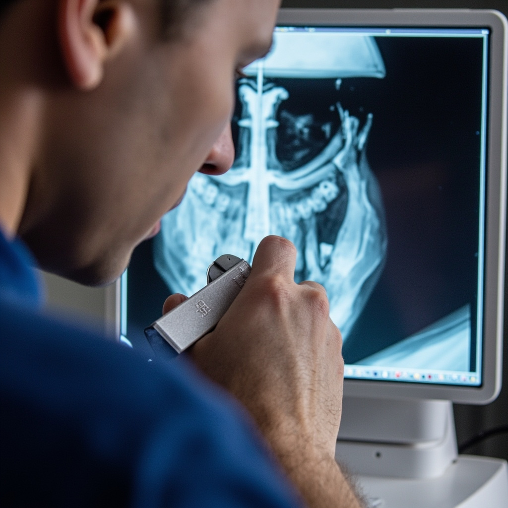
PSP phosphor imaging plates maintenance procedure

Intraoral Sensor Cleaning Protocols

Digital intraoral sensors require immediate cleaning after each patient use to prevent biofilm formation and ensure consistent image quality. The cleaning process must balance thorough disinfection with component protection.

Pre-Cleaning Preparation

Before beginning the cleaning process, ensure all personnel wear appropriate personal protective equipment, including disposable gloves and eye protection. Remove the sensor from the patient’s mouth carefully, avoiding contact with contaminated surfaces.

  • Use sterile gauze to remove visible debris
  • Handle sensors by the cable or designated grip areas only
  • Avoid touching the imaging surface directly
  • Place sensors on a clean, designated surface

Primary Cleaning Steps

The manufacturer-approved cleaning process typically involves multiple steps to ensure complete disinfection without component damage. Always consult your specific sensor manufacturer’s guidelines, as cleaning agents and procedures vary between brands.

  • Apply manufacturer-approved disinfectant wipes or solutions
  • Clean all surfaces including the sensor body and cable
  • Use gentle circular motions, avoiding excessive pressure
  • Allow appropriate contact time as specified by disinfectant manufacturer
  • Dry thoroughly with sterile lint-free cloths
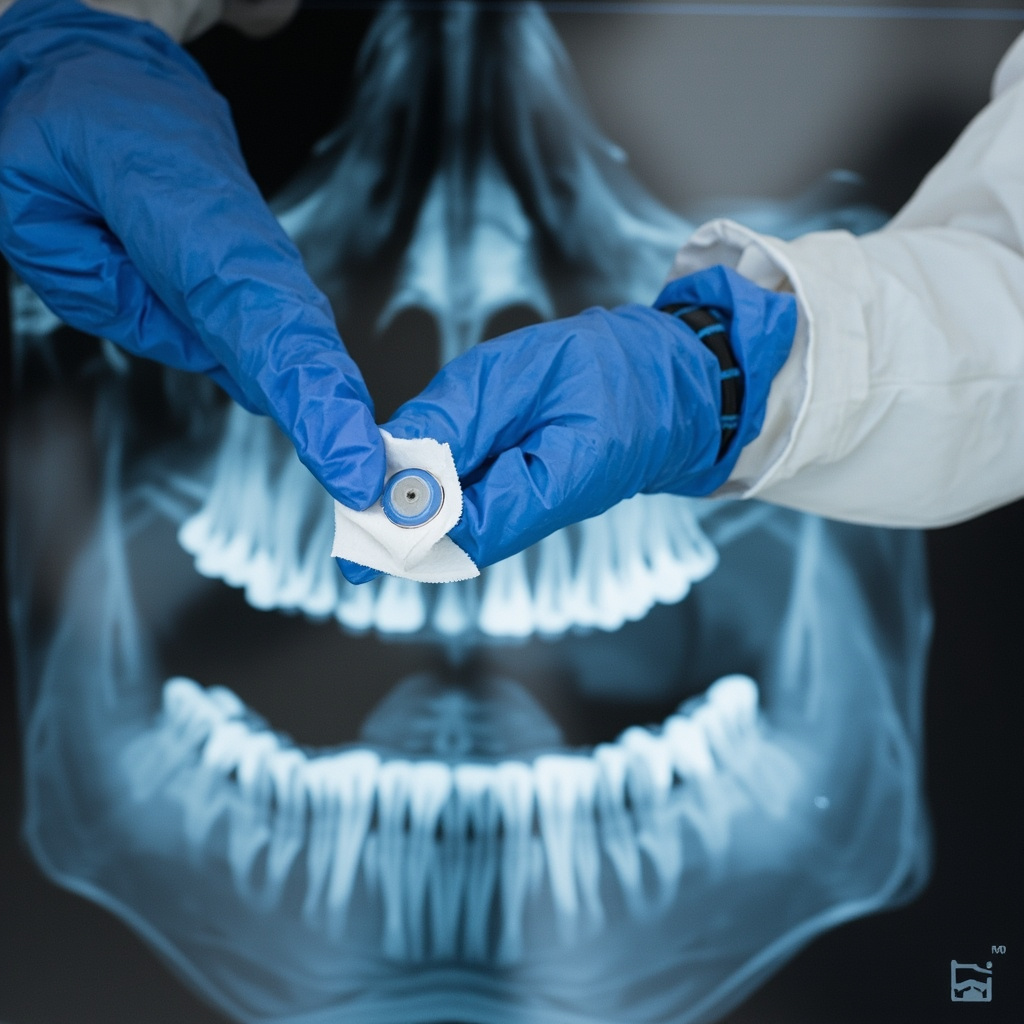
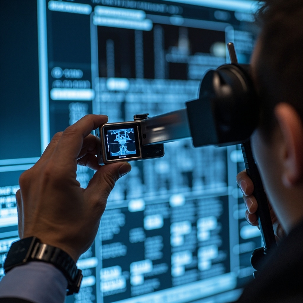
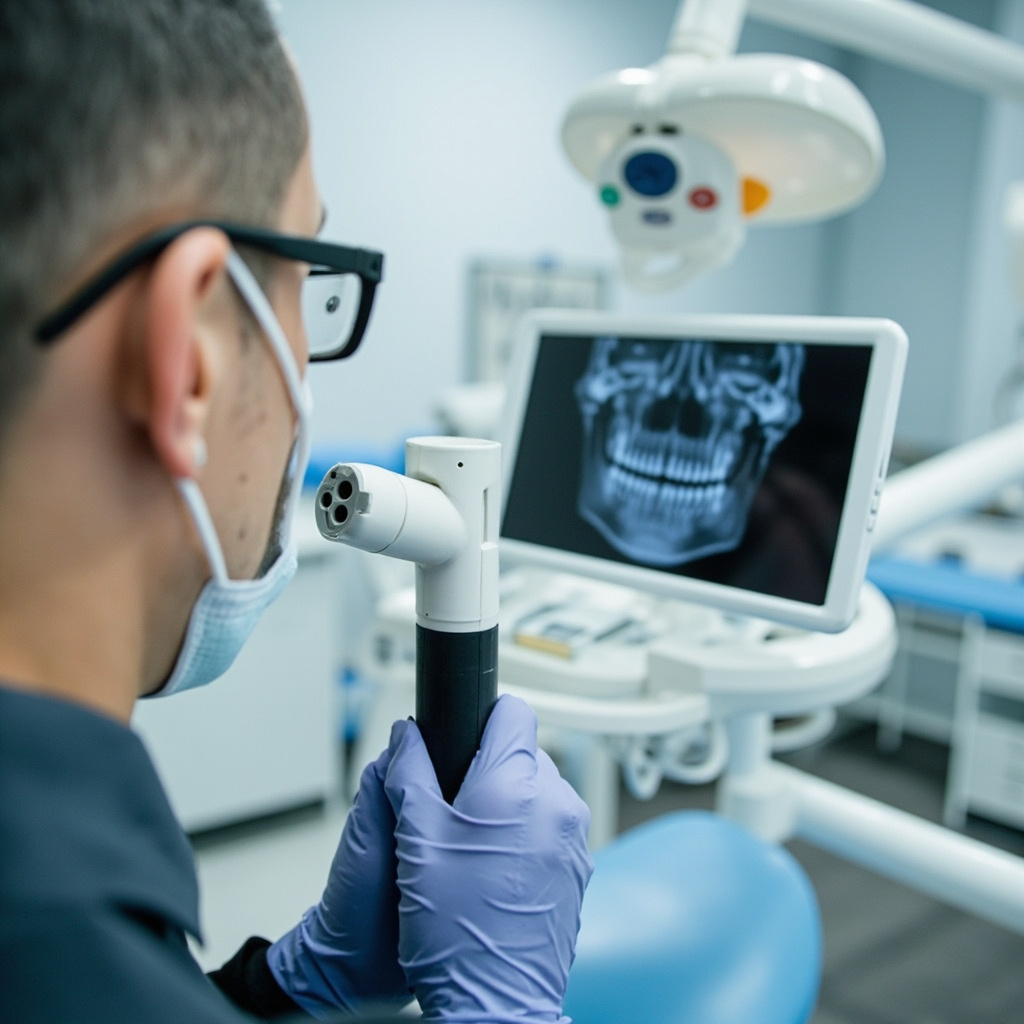
Proper digital X-ray sensor cleaning technique demonstration

PSP Plate Maintenance Procedures

Photostimulable phosphor plates require specialized care due to their sensitive phosphor coating. These reusable plates can provide thousands of exposures when properly maintained, making correct cleaning procedures essential for maximizing return on investment.

Daily Cleaning Protocol

PSP plates should be cleaned after each use and undergo daily maintenance to remove accumulated debris and prevent phosphor degradation. The cleaning process differs significantly from sensor cleaning due to the plate’s unique construction.

  • Remove plates from protective sleeves immediately after use
  • Use only manufacturer-recommended cleaning solutions
  • Clean with gentle, linear motions to avoid scratching
  • Never use alcohol-based cleaners unless specifically approved
  • Ensure complete drying before storage

Weekly Deep Cleaning

In addition to daily cleaning, PSP plates benefit from weekly deep cleaning procedures that remove accumulated residue and maintain optimal phosphor sensitivity. This process typically involves more intensive cleaning agents and longer contact times.

  • Perform visual inspection for scratches or damage
  • Use approved enzyme cleaners for protein removal
  • Follow extended contact time protocols
  • Conduct quality control testing after deep cleaning

Disinfection Agent Selection

Choosing appropriate disinfection agents is crucial for maintaining both infection control standards and equipment integrity. Not all disinfectants are suitable for digital imaging equipment, and using incorrect products can cause permanent damage.

Approved Cleaning Solutions

Most manufacturers provide specific lists of approved cleaning agents. Common approved solutions include certain quaternary ammonium compounds, glutaraldehyde-based solutions, and specialized medical device disinfectants. Always verify compatibility before use.

  • EPA-registered hospital-grade disinfectants
  • Manufacturer-specified cleaning wipes
  • pH-neutral enzyme cleaners for protein removal
  • Alcohol-based solutions (when manufacturer-approved)

Prohibited Substances

Certain chemicals can cause irreversible damage to digital imaging equipment. These substances should never be used on sensors or PSP plates, regardless of their effectiveness on other dental equipment.

  • High-concentration bleach solutions
  • Phenolic compounds
  • Iodophors (unless specifically approved)
  • Abrasive cleaners or scrubbing pads
  • Autoclave sterilization

Quality Control and Testing

Regular quality control testing ensures that cleaning procedures maintain both infection control standards and image quality. Establish routine testing protocols to identify issues before they affect patient care.

Perform weekly image quality assessments using standardized test objects to detect any cleaning-related issues. Document results and investigate any degradation in image quality immediately.

Storage and Handling

Proper storage conditions are essential for maintaining cleaned sensors and PSP plates. Store equipment in clean, dry environments away from direct sunlight and temperature extremes.

Use appropriate storage containers or sleeves to prevent contamination between uses. Implement inventory rotation systems to ensure even wear across multiple plates or sensors.

Staff Training and Compliance

Comprehensive staff training ensures consistent adherence to cleaning protocols. Provide initial training for all personnel handling digital imaging equipment, followed by regular refresher sessions and competency assessments.

Document all training activities and maintain records of compliance monitoring. Address any deviations from established protocols immediately through additional training or process modifications.

Troubleshooting Common Issues

Even with proper cleaning protocols, digital imaging equipment may develop performance issues. Understanding common problems and their solutions helps maintain optimal system performance.

Image artifacts, reduced sensitivity, or visible scratches often indicate cleaning-related problems. Implement systematic troubleshooting procedures to identify root causes and prevent recurrence.

Conclusion

Effective cleaning and maintenance of digital X-ray sensors and PSP plates requires dedicated attention to manufacturer specifications, infection control guidelines, and quality assurance protocols. By implementing comprehensive cleaning procedures and maintaining strict adherence to established protocols, dental practices can ensure optimal image quality while providing safe, effective patient care.

Regular review and updates of cleaning protocols help practices stay current with evolving technology and regulatory requirements, ultimately supporting better patient outcomes and equipment longevity.
Related Reading

Essential Preventive Maintenance Schedules for Dental X-Ray Equipment: A Comprehensive Guide

Regular preventive maintenance is the foundation of reliable dental X-ray equipment operation. A well-structured maintenance schedule not only extends equipment lifespan but also ensures consistent image quality, reduces emergency repairs, and maintains compliance with regulatory standards.

Daily Maintenance Protocols

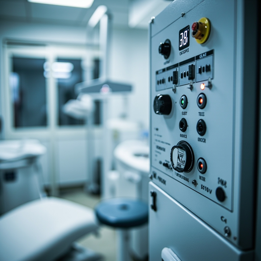
Start each day with a visual inspection of your X-ray equipment. Check for any visible damage to cables, positioning arms, and control panels. Verify that all safety interlocks are functioning properly and that exposure indicator lights are working correctly.

Clean all surfaces that come into contact with patients using appropriate disinfectants. Pay special attention to positioning guides, bite blocks, and sensor holders. Document any irregularities in your daily maintenance log.

Dental x-ray equipment control panel maintenance

Weekly Maintenance Tasks

Perform a more thorough cleaning of equipment housings and stands. Inspect all mechanical joints and positioning mechanisms for smooth operation. Check that cables are properly secured and show no signs of wear or damage.

Test the emergency stop functions and verify that exposure timers are accurate. Run a quick calibration check using standard test procedures to ensure consistent output parameters.

Monthly Comprehensive Inspections

Monthly maintenance should include detailed documentation of equipment performance parameters. Check X-ray tube housing for any signs of overheating or damage. Inspect filtration systems and collimation accuracy.

Review and update maintenance logs, noting any trends in performance or recurring issues. This is also an ideal time to verify that backup systems and safety equipment are functioning properly.

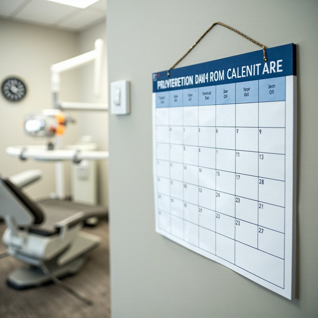
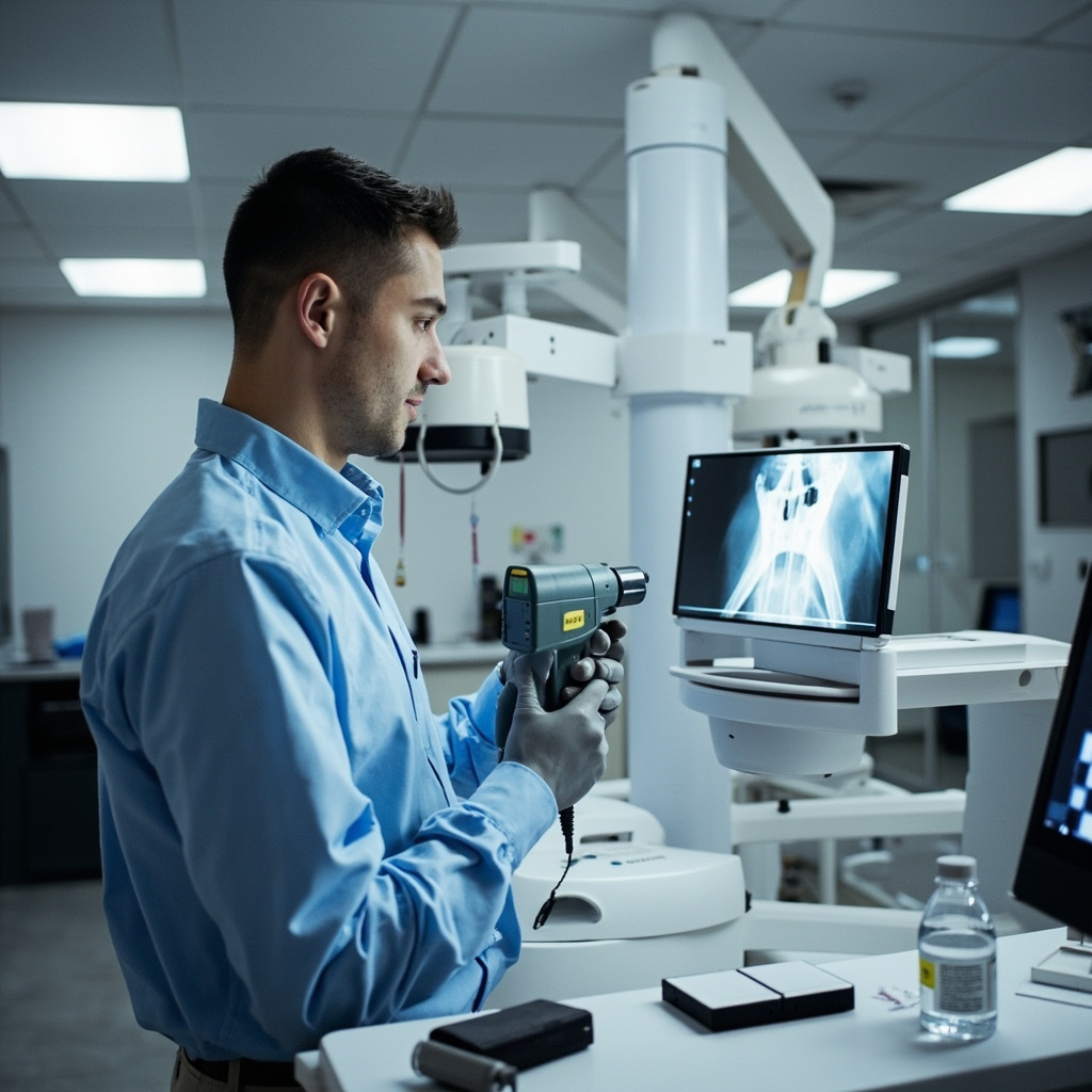
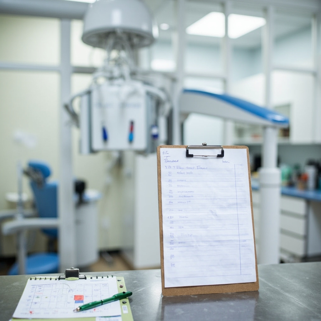
Dental office maintenance calendar schedule

Quarterly Professional Services

Schedule professional service technician visits every three months for comprehensive system evaluations. These visits should include electrical safety testing, radiation output measurements, and mechanical alignment verification.

Professional maintenance ensures compliance with regulatory requirements and identifies potential issues before they become costly repairs. Technicians can also provide valuable training updates for staff on proper equipment operation.

Annual Maintenance Requirements

Annual maintenance represents the most comprehensive evaluation of your X-ray systems. This includes complete electrical safety testing, radiation shielding assessments, and image quality evaluations.

Update all safety protocols and staff training materials based on manufacturer recommendations and regulatory changes. Plan for any major component replacements or upgrades during scheduled downtime.

Creating Your Maintenance Schedule

Develop a customized maintenance calendar that accounts for your specific equipment models and practice volume. Use digital scheduling tools to send automatic reminders for routine maintenance tasks.

Assign specific staff members responsibility for different maintenance aspects, ensuring clear accountability and consistent execution. Maintain detailed records of all maintenance activities for regulatory compliance and warranty purposes.

Cost-Benefit Analysis

Investing in preventive maintenance typically costs 3-5 times less than emergency repairs. Equipment maintained according to manufacturer specifications lasts 20-30% longer than neglected systems.

Regular maintenance also maintains image quality consistency, reducing retakes and improving patient satisfaction. The time invested in preventive care pays dividends in reduced downtime and extended equipment life.

Common Maintenance Oversights

Many practices focus only on cleaning and ignore mechanical components until problems arise. Regular lubrication of moving parts and adjustment of positioning mechanisms prevents premature wear.

Another frequent oversight is failing to document maintenance activities. Comprehensive records are essential for warranty claims, regulatory inspections, and identifying performance trends.

Establish a culture of proactive maintenance rather than reactive repairs. Your patients, staff, and bottom line will benefit from this systematic approach to equipment care.

Related Reading

Dental X-Ray Equipment Firmware Updates: Complete Management and Recovery Guide for 2026

Modern dental X-ray equipment relies heavily on firmware to operate efficiently and maintain optimal image quality. Regular firmware updates ensure your equipment performs at peak capacity, addresses security vulnerabilities, and incorporates the latest imaging enhancements. This comprehensive guide covers firmware update procedures, troubleshooting common issues, and recovery strategies for dental practices.

Understanding Firmware in Dental X-Ray Equipment

Firmware serves as the bridge between your X-ray equipment hardware and software systems. It controls exposure timing, image processing algorithms, communication protocols, and safety mechanisms. Unlike software updates that can be easily reversed, firmware changes directly modify the equipment operating system, making proper procedures essential.

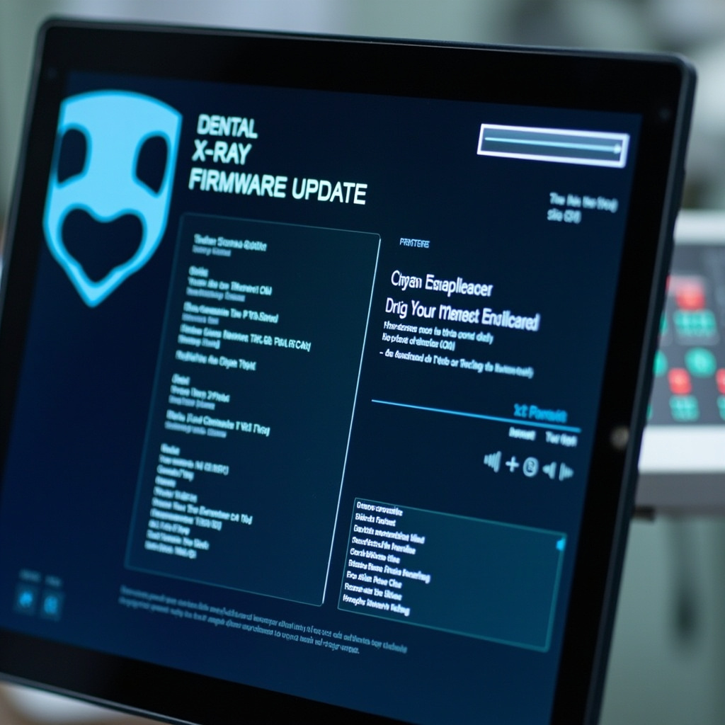
Firmware update interface on dental X-ray equipment

Most dental X-ray manufacturers release firmware updates quarterly to address performance improvements, security patches, and regulatory compliance requirements. These updates typically include enhanced image processing algorithms, improved network connectivity, and refined calibration procedures.

Pre-Update Preparation and Best Practices

Before initiating any firmware update, establish a comprehensive backup strategy. Document current firmware versions, calibration settings, and system configurations. Create recovery media using manufacturer-provided tools, and ensure you have stable power supply with uninterrupted power source (UPS) protection.

Schedule firmware updates during non-patient hours to avoid disrupting clinical operations. Notify all staff members about planned maintenance windows and establish contingency protocols for emergency imaging needs during the update process.

Essential Pre-Update Checklist

  • Verify current firmware version and compatibility requirements
  • Download latest firmware from manufacturer verified sources only
  • Test network connectivity and bandwidth stability
  • Backup existing configuration files and calibration data
  • Prepare recovery USB drives with emergency firmware
  • Document all custom settings and user preferences

Firmware Update Procedures by Equipment Type

Different X-ray equipment types require specific update procedures. Intraoral sensors typically update through USB connections or network protocols, while panoramic units often require direct console access. CBCT systems generally use network-based updates with extended installation times due to their complex imaging algorithms.

Always follow manufacturer-specific procedures precisely. Generic update methods can result in equipment failure, warranty voidance, and potential safety hazards. Maintain documentation throughout the process for regulatory compliance and future reference.

Network-Based Updates

Most modern dental X-ray equipment supports network-based firmware updates. These systems download updates directly from manufacturer servers, verify digital signatures, and install automatically. Monitor network traffic during updates to ensure stable connections and avoid interruptions.

Common Firmware Update Problems and Solutions

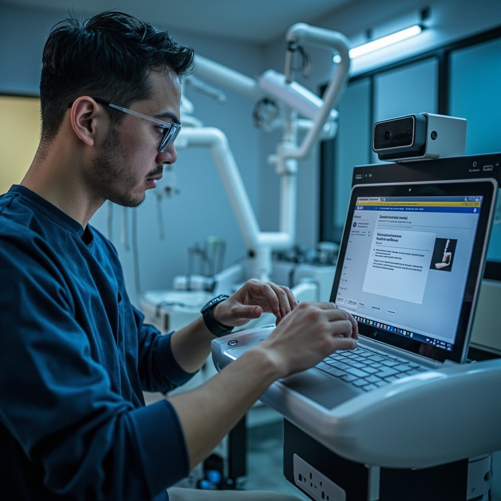
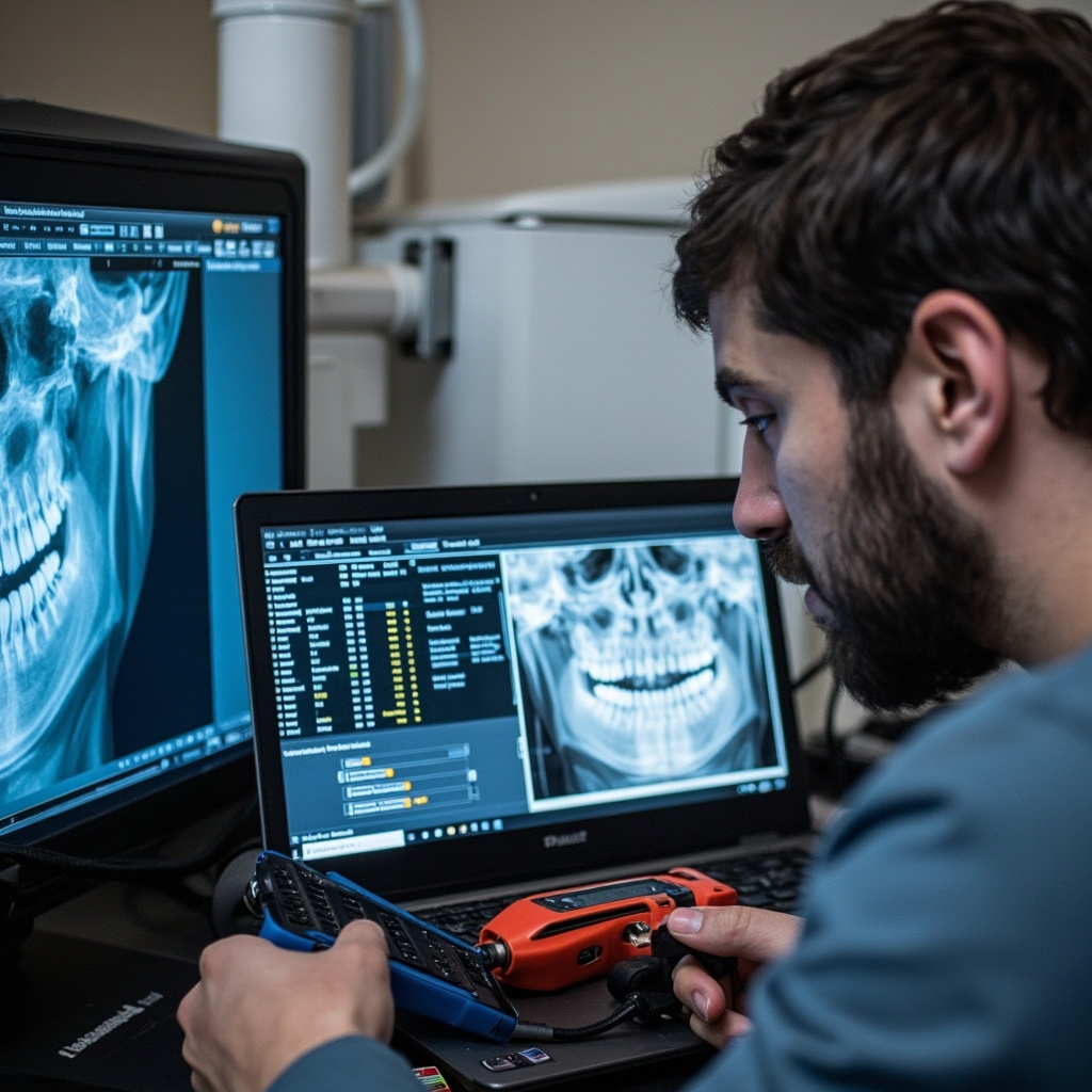
Technician troubleshooting X-ray equipment firmware issues

Firmware update failures can occur due to power interruptions, network instability, corrupted download files, or incompatible hardware configurations. Understanding common failure modes enables rapid diagnosis and resolution, minimizing equipment downtime.

Update Interruption Recovery

If firmware updates are interrupted by power loss or network disconnection, most equipment enters recovery mode automatically. This protective mechanism prevents complete system failure by maintaining core functionality while allowing firmware restoration.

Recovery procedures typically involve connecting recovery media to equipment USB ports and following manufacturer-specific boot sequences. Some systems require specific key combinations during startup to access recovery modes.

Version Compatibility Issues

Installing incompatible firmware versions can cause system instability, imaging artifacts, or complete equipment failure. Always verify hardware model numbers, software version requirements, and regional compliance standards before proceeding with updates.

Maintain detailed equipment inventories including model numbers, serial numbers, and current firmware versions. This documentation streamlines compatibility verification and simplifies support interactions with manufacturers.

Recovery and Rollback Strategies

When firmware updates fail or cause unexpected issues, rapid recovery procedures restore equipment functionality. Most manufacturers provide emergency recovery tools and procedures for critical situations requiring immediate equipment restoration.

Factory reset procedures return equipment to original firmware versions but eliminate all custom configurations and calibration data. Use this option only when other recovery methods fail, and ensure you have complete backup documentation for reconfiguration.

Creating Recovery Media

Prepare recovery USB drives before problems occur. Download manufacturer recovery tools and emergency firmware images to dedicated storage devices. Test recovery procedures during scheduled maintenance to verify functionality and familiarity with processes.

Label recovery media clearly with equipment model numbers, firmware versions, and creation dates. Store recovery drives in secure locations accessible during emergency situations but protected from environmental damage.

Post-Update Verification and Testing

After successful firmware updates, comprehensive testing ensures all systems function correctly. Verify imaging quality, calibration accuracy, network connectivity, and safety interlocks before returning equipment to clinical service.

Perform test exposures using standardized phantoms to verify image quality consistency. Check exposure timing accuracy, dose output stability, and image processing functionality. Document all test results for regulatory compliance and quality assurance records.

Performance Validation

Compare post-update performance metrics with baseline measurements. Monitor exposure consistency, image noise levels, and processing speeds to identify any degradation requiring attention. Address performance issues immediately to maintain optimal patient care standards.

Ongoing Firmware Management

Establish systematic firmware management procedures including regular update schedules, security monitoring, and performance tracking. Subscribe to manufacturer notification services for critical updates and security advisories.

Maintain current firmware inventories across all equipment and coordinate updates to avoid compatibility conflicts between interconnected systems. Plan update schedules to minimize clinical disruption while maintaining security compliance.

Document all firmware changes with detailed logs including dates, versions, personnel involved, and any issues encountered. This documentation supports regulatory audits, warranty claims, and troubleshooting future problems.

Related Reading

Dental X-Ray Equipment Quality Assurance Testing: Essential Calibration Procedures for 2026

Quality assurance (QA) testing for dental X-ray equipment ensures optimal image quality while maintaining patient and operator safety through precise radiation dose control. Regular calibration procedures are essential for regulatory compliance and clinical excellence.

Understanding QA Testing Requirements

Quality assurance protocols establish baseline values during equipment installation and require ongoing periodic testing to maintain performance standards. The Conference of Radiation Control Program Directors (CRCPD) provides comprehensive guidelines for dental X-ray equipment testing.

Modern dental practices must implement structured QA programs that include:

  • Radiation output consistency measurements
  • Beam quality assessments
  • Timer accuracy verification
  • Collimation alignment testing
  • Patient dose optimization

Essential Calibration Equipment

QA phantom test tool for dental x-ray calibration

Professional QA testing requires specialized equipment including dosimetry phantoms, radiation measurement devices, and beam alignment tools. These instruments ensure accurate assessment of X-ray system performance parameters.

Key testing equipment includes:

  • Step-wedge phantoms for image quality assessment
  • Ion chambers for radiation output measurement
  • Digital dosimeters for real-time dose monitoring
  • Beam alignment devices for collimation testing
  • Timer test tools for exposure accuracy verification

Critical Testing Procedures

Radiation Output Testing

Output consistency testing verifies that radiation exposure remains stable across different technique settings. Measurements should fall within ±10% of baseline values established during installation.

Testing protocol involves:

  • Positioning dosimeter at standard distance
  • Using identical exposure parameters
  • Recording multiple measurements for statistical analysis
  • Comparing results to baseline reference values

Beam Quality Assessment

Half-value layer (HVL) measurements determine beam filtration adequacy and energy characteristics. Proper beam quality ensures optimal image contrast while minimizing patient exposure.

Timer Accuracy Verification

Exposure timer accuracy directly affects radiation dose and image quality. Digital timers should maintain accuracy within ±10% of selected exposure times.

Digital radiography quality control chart and test results

Documentation and Compliance

Comprehensive documentation of all QA testing results is mandatory for regulatory compliance and clinical quality management. Records must include test dates, measured values, reference standards, and corrective actions taken.

Documentation requirements include:

  • Baseline measurement records from installation
  • Periodic testing results with dates and signatures
  • Calibration certificates for test equipment
  • Maintenance logs and service records
  • Staff training documentation

Frequency and Scheduling

QA testing frequency depends on equipment type, usage patterns, and regulatory requirements. Most jurisdictions require annual comprehensive testing with more frequent checks for high-volume practices.

Recommended testing schedule:

  • Daily: Visual inspection and basic function checks
  • Weekly: Image quality assessment using test phantoms
  • Monthly: Dosimetry spot checks and timer verification
  • Annually: Comprehensive QA testing by qualified professionals

Troubleshooting Common Issues

QA testing often reveals performance drift requiring corrective action. Common issues include timer inaccuracy, output instability, and beam alignment problems.

When measurements fall outside acceptable tolerances:

  • Discontinue patient use immediately
  • Document the deviation and investigation steps
  • Contact qualified service personnel
  • Implement temporary alternative imaging protocols if needed
  • Verify repairs with follow-up testing before clinical use

Future of Dental QA

Emerging technologies are transforming dental X-ray QA with automated testing systems, cloud-based data management, and AI-assisted analysis. These innovations promise more efficient, accurate, and comprehensive quality assurance programs.

Advanced QA systems now offer real-time monitoring, predictive maintenance alerts, and integrated compliance reporting, streamlining quality management for modern dental practices.

Related Reading

NEC Article 660: Essential Electrical Grounding Requirements for Dental X-Ray Equipment

Proper electrical grounding is critical for dental X-ray equipment safety and regulatory compliance. National Electrical Code (NEC) Article 660 establishes specific requirements that service technicians and dental practices must follow to ensure safe installation and operation.

Understanding NEC Article 660 Requirements

Article 660 of the National Electrical Code specifically addresses X-ray equipment installations in healthcare facilities. These regulations protect both patients and staff from electrical hazards while ensuring equipment operates reliably. The code mandates that all high-voltage components must be properly grounded and enclosed.

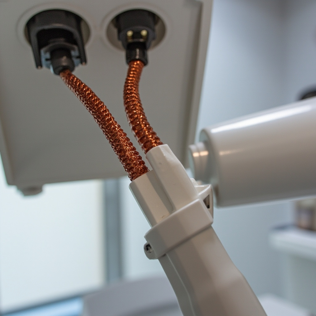
Dental X-ray grounding connections

Key Grounding Requirements

All X-ray equipment must have adequate grounding connections to prevent electrical shock hazards. The equipment grounding conductor must be sized according to NEC Table 250.122 based on the overcurrent protection device rating. For most dental X-ray units, this typically requires a minimum 12 AWG copper grounding conductor.

  • High-voltage enclosures: All components operating above 1,000 volts must be enclosed in grounded metal cabinets
  • Control circuits: Low-voltage control panels require proper grounding connections
  • Exposed metal parts: Any accessible metallic surfaces must be bonded to the equipment grounding system
  • Disconnect switches: All disconnect means must be readily accessible and properly grounded

Installation and Compliance Guidelines

Proper installation begins with verifying adequate electrical supply and grounding infrastructure. The electrical panel feeding X-ray equipment must have sufficient capacity and proper grounding electrode connections. Service technicians should always verify ground fault circuit interrupter (GFCI) protection where required by local codes.

Grounding Electrode Connections

The grounding electrode system forms the foundation of electrical safety. This includes connections to building steel, concrete-encased electrodes (Ufer grounds), ground rods, or water pipe electrodes as available. Multiple electrodes must be bonded together to create an effective grounding electrode system.

NEC compliance safety labels

Common Installation Mistakes

Service technicians frequently encounter grounding violations that compromise safety and code compliance. Understanding these common errors helps ensure proper installation from the start.

Inadequate Conductor Sizing

Using undersized grounding conductors is a serious code violation. The equipment grounding conductor must be sized according to the overcurrent protection device, not the equipment nameplate current. This ensures adequate fault current capacity for proper circuit breaker operation.

Missing Bonding Connections

All metallic enclosures and accessories must be bonded together and to the main grounding system. This includes X-ray tube housings, control cabinets, and any auxiliary equipment. Missed bonding connections create dangerous voltage potentials during fault conditions.

Testing and Verification Procedures

After installation, comprehensive testing verifies grounding system integrity. This includes measuring ground resistance, verifying continuity between all bonded components, and checking for proper GFCI operation where applicable.

  • Ground resistance testing: Measure resistance from equipment ground to building electrode system
  • Continuity verification: Test all bonding connections for low resistance paths
  • Insulation testing: Verify adequate insulation between current-carrying conductors and ground
  • GFCI testing: Confirm proper ground fault protection operation

Documentation Requirements

Maintain detailed records of all grounding measurements and test results. Many jurisdictions require documented proof of NEC compliance before issuing operating permits. These records also prove valuable for troubleshooting future electrical issues.

Maintenance and Ongoing Compliance

Grounding systems require periodic inspection and testing to maintain safety and code compliance. Corrosion, mechanical damage, or modifications can compromise grounding effectiveness over time.

Annual testing should include visual inspection of all accessible grounding connections, resistance measurements, and verification that no unauthorized modifications have been made. Any discovered deficiencies must be corrected immediately to maintain safe operating conditions.

Understanding and implementing NEC Article 660 requirements protects both equipment and personnel while ensuring regulatory compliance. Proper grounding installation and maintenance prevents electrical hazards and supports reliable X-ray equipment operation in dental practices.

Related Reading

Dental X-Ray Timer Circuit Diagnosis: Troubleshooting Communication and Control Board Failures

Timer circuit failures in dental X-ray equipment can cause inconsistent exposures, communication errors, and complete system shutdowns. These sophisticated control boards manage exposure timing, coordinate with power systems, and maintain safety protocols. When timer circuits malfunction, proper diagnostic procedures are essential for effective repair.

Understanding Timer Circuit Architecture

Modern dental X-ray systems typically use dual-board configurations with separate timer and power control circuits. The timer board manages exposure duration, safety interlocks, and communication with the main control system. Power boards handle high-voltage generation and distribution to the X-ray tube.

Timer circuit board components

Communication between these boards occurs through dedicated signal cables, often 4-pin connectors carrying digital control signals. When this communication fails, the system may display error codes, produce inconsistent exposures, or refuse to operate entirely.

Common Timer Circuit Failure Symptoms

Several indicators point to timer circuit problems:

  • No exposure activation: System powers on but fails to initiate X-ray production when triggered
  • Inconsistent exposure times: Actual exposure duration varies significantly from settings
  • Communication error codes: Display shows timer-related fault messages
  • Safety interlock failures: System bypasses or incorrectly triggers safety systems
  • Display anomalies: Timer readouts show incorrect values or fail to update

Diagnostic Procedures

Initial System Assessment

Begin diagnostics by powering down the system completely, waiting for capacitor discharge, then restarting. Monitor the startup sequence for error messages or abnormal behavior. Check all external connections, including wall power and any portable battery systems.

Communication Cable Testing

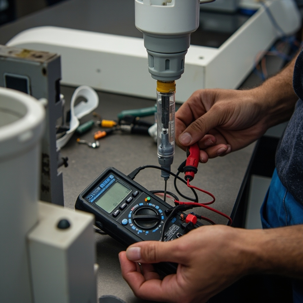
The most common timer circuit failure involves communication cable problems. These cables carry low-voltage digital signals between the timer and power boards. Test continuity on each wire of the communication cable using a multimeter.

Technician testing timer circuit connections

Measure resistance across each conductor – readings should show near-zero ohms for intact wires. High resistance or open circuits indicate cable damage. Pay particular attention to wire #2, which commonly carries critical timing signals.

Board-Level Diagnostics

If cable testing confirms continuity, the problem likely exists within the timer or power control boards themselves. Look for diagnostic LEDs on the timer board – these typically indicate power status, communication activity, and fault conditions.

Check voltage levels at key test points when available. Timer circuits typically operate at 5V or 12V DC logic levels. Verify these voltages remain stable during operation attempts.

Repair Procedures

Communication Cable Replacement

When cable testing reveals continuity problems, replacement is usually the most cost-effective solution. Ensure replacement cables match the original pin configuration and wire gauge. Improper cables can cause new communication issues or safety hazards.

Circuit Board Replacement

Failed timer boards require professional replacement, as these contain calibrated timing circuits and safety-critical components. Before replacing boards:

  • Document all switch positions and jumper settings
  • Photograph cable connections for reference
  • Record any calibration values displayed on labels
  • Verify replacement board compatibility with your specific model

Safety Considerations

Timer circuit repair involves high-voltage systems and radiation safety equipment. Never bypass safety interlocks or attempt repairs while the system is energized. Use proper lockout/tagout procedures and ensure only qualified technicians perform internal repairs.

After any timer circuit repair, conduct thorough exposure testing to verify proper timing accuracy and safety system function. Document all timing measurements for regulatory compliance.

Preventive Maintenance

Regular inspection of communication cables can prevent many timer circuit failures. Check for cable stress at connection points, especially where cables bend or flex during normal operation. Replace cables showing signs of wear before failure occurs.

Maintain clean, dry conditions around control boards. Moisture and dust can cause communication issues and premature component failure. Schedule periodic calibration checks to ensure timing accuracy remains within specifications.

Related Reading

X-Ray Tube Heat Management: Essential Anode Cooling Systems for Dental Equipment

Proper heat management in dental X-ray tubes is crucial for optimal performance, extended equipment lifespan, and consistent image quality. The anode, which absorbs nearly 99% of the electron beam energy as heat, requires sophisticated cooling systems to prevent overheating and maintain diagnostic accuracy.

Understanding how these cooling systems work and implementing proper maintenance protocols can significantly reduce equipment failures and costly downtime in dental practices.

Understanding X-Ray Tube Heat Generation

When electrons strike the tungsten target on the anode, only about 1% of the energy converts to X-rays. The remaining 99% becomes heat that must be dissipated efficiently to prevent damage to the tube components.

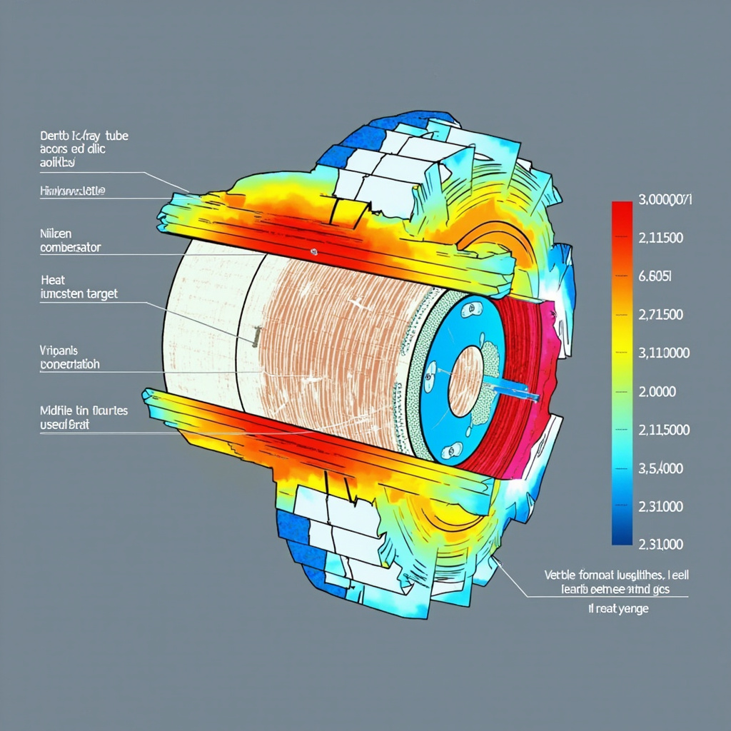
Cross-section diagram of dental X-ray tube anode

The heat concentration at the focal spot creates temperatures exceeding 1000°C during exposures. Without proper cooling, this extreme heat can cause:

  • Tungsten target deterioration
  • Anode warping or cracking
  • Vacuum loss in the tube envelope
  • Reduced X-ray output and image quality
  • Complete tube failure requiring expensive replacement

Types of Anode Cooling Systems

Rotating Anode Systems

Most modern dental X-ray equipment uses rotating anodes that distribute heat over a larger surface area. The tungsten disc rotates at 3,000 to 10,000 RPM, spreading the electron beam impact across the entire target track rather than concentrating it on a single spot.

Key components include:

  • Rotor assembly with high-temperature bearings
  • Stator windings for electromagnetic rotation
  • Heat-resistant target materials (tungsten-rhenium alloys)
  • Cooling fins integrated into the anode stem

Oil-Immersed Housing Cooling

The X-ray tube housing contains specialized dielectric oil that serves multiple functions:

  • Electrical insulation between components
  • Heat absorption from the tube assembly
  • Heat transfer to external cooling fins or radiators
  • Vibration dampening during operation

Maintenance and Monitoring Protocols

Regular monitoring of cooling system performance prevents unexpected failures and extends equipment life. Key maintenance tasks include:

Technician performing X-ray cooling system maintenance

Temperature Monitoring

Modern X-ray systems include thermal sensors that track anode and housing temperatures. Establish baseline readings and monitor for gradual increases that indicate cooling system degradation.

  • Check temperature readings daily during startup
  • Log maximum temperatures reached during busy periods
  • Set alerts for temperatures exceeding manufacturer specifications
  • Schedule immediate service if temperatures trend upward

Cooling System Inspection

Visual inspection of cooling components should be performed monthly:

  • Clean dust and debris from cooling fins and vents
  • Check oil levels and clarity (if accessible)
  • Inspect fan operation and airflow patterns
  • Verify proper ventilation around equipment
  • Test cooling system alarms and safety interlocks

Signs of Cooling System Problems

Early detection of cooling issues prevents costly tube replacements. Watch for these warning signs:

  • Longer warmup times before equipment reaches ready status
  • Reduced maximum technique factors available
  • Frequent thermal protection shutdowns
  • Unusual noise from cooling fans or oil circulation pumps
  • Visible oil leaks around tube housing
  • Image quality degradation or artifacts

Optimizing Heat Management

Dental practices can implement several strategies to minimize heat stress on X-ray tubes:

  • Technique Selection: Use lowest practical kVp and mAs combinations for adequate image quality
  • Exposure Timing: Allow adequate cooling time between multiple exposures
  • Environmental Control: Maintain proper room temperature and ventilation
  • Preventive Loading: Gradually increase technique factors during initial daily use
  • Regular Calibration: Ensure accurate exposure parameters to prevent unnecessary heat generation

Modern Cooling Innovations

Recent advances in X-ray tube cooling technology include:

  • Liquid metal jet anodes for ultra-high heat capacity
  • Advanced heat exchanger designs with improved efficiency
  • Real-time thermal modeling for predictive maintenance
  • Smart cooling systems that adjust based on workload patterns
  • Composite anode materials with superior thermal properties

Conclusion

Effective heat management in dental X-ray equipment requires understanding the thermal challenges, implementing proper cooling systems, and maintaining vigilant monitoring protocols. By prioritizing anode cooling system maintenance, dental practices can maximize equipment reliability, reduce operating costs, and ensure consistent diagnostic image quality.

Regular training of staff on thermal management principles and cooling system operation creates a foundation for long-term equipment success and patient care excellence.

Related Reading

Collimator Beam Alignment Testing: Essential Maintenance Guide for Dental X-Ray Equipment

Proper beam alignment in dental X-ray equipment is critical for image quality and radiation safety. The collimator system controls the size and direction of the X-ray beam, making regular alignment testing an essential part of preventive maintenance protocols.

Understanding Collimator Function

The collimator assembly contains lead shutters that shape and limit the X-ray beam to the area of interest. When properly aligned, it ensures the beam is perpendicular to the image receptor and centered within the light field indicators.

Dental technician using beam alignment test tool

Common Alignment Issues

Several factors can affect collimator beam alignment:

  • Mechanical wear: Tube head mounting brackets can loosen over time
  • Lead leaf damage: Collimator shutters may become misaligned or damaged
  • Vibration effects: Equipment movement during transport or heavy use
  • Temperature fluctuations: Expansion and contraction affecting precision components

Testing Procedures

Professional alignment testing should be performed quarterly using specialized beam alignment test tools. These devices provide a simple method to verify that the X-ray beam is perpendicular to the image receptor and properly centered.

Required Equipment

Standard alignment testing requires:

  • Beam alignment test device
  • Image receptor or test film
  • Positioning indicators
  • Measurement tools for deviation analysis

X-ray collimator lead leaf adjustment mechanism

Rectangular Collimation Benefits

Modern rectangular collimation systems offer significant advantages over traditional circular collimators. They reduce patient radiation exposure by up to 60% while maintaining diagnostic image quality. However, they require more precise alignment procedures.

Alignment Challenges with Rectangular Collimators

Rectangular systems present unique alignment considerations:

  • Four-point alignment verification required
  • Rotation adjustments for proper sensor orientation
  • Enhanced sensitivity to misalignment
  • Specialized positioning devices needed

Professional Service Recommendations

While basic visual inspections can be performed in-house, comprehensive alignment testing requires specialized equipment and training. Annual professional calibration ensures compliance with safety regulations and optimal equipment performance.

Service Schedule

Recommended maintenance intervals:

  • Monthly: Visual inspection of collimator housing
  • Quarterly: Basic alignment verification
  • Annually: Professional calibration and adjustment
  • As needed: After equipment relocation or impact

Proper collimator maintenance ensures consistent image quality, reduces retakes, and maintains radiation safety standards. Regular testing protocols help identify alignment issues before they affect diagnostic capability or patient safety.

Related Reading

Handheld Dental X-Ray Devices: Safety Protocols and Troubleshooting Guide for 2026

Handheld dental X-ray devices have revolutionized dental radiography by providing portability, flexibility, and enhanced patient care in various clinical settings. However, their unique operating characteristics and safety requirements demand specific protocols and troubleshooting approaches to ensure optimal performance and regulatory compliance.

Understanding Handheld X-Ray Technology

Handheld dental X-ray units represent a significant advancement in portable radiographic technology. Unlike traditional wall-mounted systems, these devices integrate the X-ray tube, power supply, and control systems into a compact, battery-operated unit weighing typically between 4-6 pounds.

Key technological features include:

  • Rechargeable lithium-ion battery systems
  • Digital exposure controls with preset technique charts
  • Integrated radiation shielding and backscatter protection
  • LED status indicators and audible feedback systems
  • Wireless connectivity for digital sensor integration

2026 Safety Regulations and Compliance

Handheld X-ray device controls and safety features

The FDA and state regulatory agencies have established comprehensive guidelines for handheld X-ray device operation in 2026. These regulations address both operator safety and patient protection through specific performance standards.

Operator Safety Requirements

All dental staff operating handheld X-ray devices must maintain a minimum 6-foot distance during exposure or utilize appropriate radiation protection barriers. Personal dosimetry monitoring is mandatory for all operators, with quarterly dose reports required for regulatory compliance.

Device Registration and Inspection

Handheld X-ray units require annual registration with state radiation control programs and biennial performance inspections. Documentation must include:

  • Serial numbers and model specifications
  • Exposure technique validation records
  • Quality assurance test results
  • Staff training certifications
  • Incident reporting protocols

Essential Safety Protocols

Implementing comprehensive safety protocols ensures both regulatory compliance and optimal clinical outcomes. These protocols address equipment handling, patient positioning, and exposure procedures.

Pre-Exposure Checklist

Before each use, operators must verify device functionality through systematic checks:

  • Battery charge level (minimum 75% recommended)
  • Proper sensor connection and calibration
  • Exposure timer accuracy verification
  • Radiation shielding integrity inspection
  • Patient positioning and stabilization

ALARA Principle Implementation

The “As Low As Reasonably Achievable” principle remains fundamental to handheld X-ray operations. This includes optimizing exposure parameters based on patient age, anatomy, and diagnostic requirements while maintaining image quality standards.

Common Troubleshooting Issues

Quality assurance testing for handheld X-ray devices

Handheld X-ray devices, while reliable, can experience various technical issues that affect performance and image quality. Understanding common problems and their solutions minimizes downtime and maintains clinical efficiency.

Battery and Power Issues

Battery-related problems represent the most frequent handheld X-ray malfunctions. Symptoms include:

  • Insufficient exposure power resulting in underexposed images
  • Premature battery depletion during procedures
  • Inconsistent exposure timing
  • Device shutdown during operation

Solutions: Implement daily battery charging protocols, monitor charge cycles, and replace batteries according to manufacturer specifications. Most lithium-ion batteries require replacement after 500-800 charge cycles.

Exposure Control Malfunctions

Digital control systems may experience calibration drift or component failure, affecting exposure accuracy. Warning signs include:

  • Inconsistent image density across multiple exposures
  • Error codes displayed on control panel
  • Failure to complete exposure cycles
  • Unusual heating of device housing

Sensor Communication Problems

Wireless connectivity issues between handheld devices and digital sensors can disrupt workflow efficiency. Common symptoms include:

  • Failed image capture despite successful exposure
  • Delayed image transfer to computer systems
  • Intermittent connection dropouts
  • Sensor calibration errors

Quality Assurance Procedures

Regular quality assurance testing ensures consistent device performance and regulatory compliance. The American Dental Association recommends monthly QA testing for handheld X-ray units.

Monthly Performance Tests

Essential monthly tests include:

  • Exposure timer accuracy verification
  • Radiation output consistency measurement
  • Image quality assessment using standardized phantoms
  • Battery performance evaluation
  • Sensor calibration verification

Annual Professional Inspections

Certified medical physics professionals should conduct comprehensive annual inspections covering radiation safety, mechanical integrity, and electrical systems. These inspections satisfy regulatory requirements and identify potential issues before they affect clinical operations.

Best Practices for 2026

Optimal handheld X-ray device utilization requires adherence to established best practices developed through extensive clinical experience and regulatory guidance.

Staff Training and Certification

All operators must complete manufacturer-specific training programs and maintain current radiation safety certifications. Training should emphasize:

  • Proper device handling and positioning techniques
  • Patient safety protocols and communication
  • Emergency procedures and incident reporting
  • Quality assurance testing procedures
  • Regulatory compliance requirements

Maintenance Scheduling

Preventive maintenance programs significantly extend device lifespan and maintain performance standards. Recommended maintenance intervals include:

  • Daily: Battery charging and visual inspection
  • Weekly: Sensor calibration and connectivity testing
  • Monthly: Performance quality assurance testing
  • Quarterly: Professional inspection and calibration
  • Annually: Comprehensive system evaluation and certification

Future Developments

Handheld X-ray technology continues evolving with improvements in battery technology, imaging sensors, and artificial intelligence integration. Emerging developments for 2026 and beyond include enhanced wireless protocols, automated exposure optimization, and integrated image analysis capabilities.

Staying current with technological advances ensures practices maintain competitive advantages while providing optimal patient care through the latest diagnostic imaging capabilities.

Related Reading

Dental X-Ray Power Supply Issues: Diagnosing and Resolving Voltage Problems

Power supply problems can severely impact dental X-ray equipment performance, leading to inconsistent image quality, equipment failures, and costly downtime. Understanding how to diagnose and resolve voltage-related issues is essential for maintaining reliable X-ray operations in your dental practice.

Common Power Supply Problems in Dental X-Ray Equipment

Dental X-ray systems are sensitive to electrical fluctuations and require stable power to function optimally. The most frequent power-related issues include:

  • Voltage fluctuations: Inconsistent power delivery causing exposure variations
  • Power surges: Sudden voltage spikes that can damage sensitive components
  • Brownouts: Temporary voltage drops that affect image quality
  • Electrical noise: Interference from other equipment causing image artifacts
  • Ground faults: Improper grounding leading to safety and performance issues

Electrical multimeter testing dental X-ray equipment voltage

Diagnostic Procedures for Power Supply Issues

Proper diagnosis begins with systematic testing of your electrical infrastructure:

Voltage Testing

Use a quality multimeter to measure:

  • Supply voltage at the main panel (should be 208-240V for most dental X-ray units)
  • Voltage at the X-ray unit connection point
  • Voltage under load during X-ray exposures
  • Ground continuity and resistance

Load Analysis

Examine your electrical system capacity:

  • Calculate total amperage draw during X-ray operation
  • Identify other high-draw equipment on the same circuit
  • Check for proper circuit sizing and breaker ratings
  • Verify adequate power distribution for peak demand periods

Resolution Strategies

Once you’ve identified power supply issues, implement these targeted solutions:

Voltage Stabilization

Install voltage regulation equipment to ensure consistent power delivery:

  • Automatic voltage regulators (AVRs): Compensate for minor voltage fluctuations
  • Uninterruptible power supplies (UPS): Provide clean, consistent power and backup during outages
  • Isolation transformers: Reduce electrical noise and provide clean power

Voltage stabilizer and power surge protector devices

Circuit Improvements

Upgrade your electrical infrastructure when necessary:

  • Install dedicated circuits for X-ray equipment
  • Upgrade to appropriate wire gauge for your equipment’s amperage requirements
  • Ensure proper grounding throughout the electrical system
  • Add surge protection devices at the panel and equipment level

Preventive Maintenance

Regular maintenance prevents many power-related problems:

  • Monthly inspections: Check all power connections, cables, and terminations
  • Quarterly testing: Measure voltage, current, and ground resistance
  • Annual assessments: Comprehensive electrical system evaluation by qualified technicians
  • Environmental monitoring: Track temperature and humidity in equipment areas

When to Call Professionals

While some basic troubleshooting can be performed in-house, certain situations require professional intervention:

  • Repeated power supply failures or equipment damage
  • Complex electrical system modifications or upgrades
  • Safety concerns related to grounding or electrical hazards
  • Regulatory compliance issues or inspection requirements

Cost-Benefit Analysis

Investing in power quality solutions pays dividends through:

  • Reduced downtime: Fewer equipment failures and service calls
  • Extended equipment life: Protection from electrical stress and damage
  • Improved image quality: Consistent exposures and diagnostic reliability
  • Lower operating costs: Reduced energy consumption and maintenance expenses

Power supply issues don’t have to disrupt your dental practice operations. With proper diagnosis, targeted solutions, and preventive maintenance, you can ensure reliable X-ray performance and protect your investment in imaging equipment. Regular monitoring and professional support when needed will keep your dental X-ray systems operating at peak efficiency.

Related Reading